
Analysis of the “Air Blockage” Issue in Thermal Inkjet Printheads
The “air blockage” issue in thermal inkjet printheads is usually caused by gas entering the liquid channel or pressure imbalance within the ink system. The following outlines the main causes and corresponding solutions.
I. Analysis of Common Causes
1. Gas Ingress
After the equipment stops operating, if the pipeline is not purged in time, residual gas mixes with the liquid and forms air blockages in the ink path.
2. Insufficient Ink Defoaming Performance
If the defoaming agent in the ink becomes ineffective or the formulation is improper, bubbles may accumulate in the ink path and enter the printhead, causing air blockage.
Bubbles may also be drawn into the printhead due to pressure fluctuations in the ink circulation system, such as air leakage in the negative pressure system or pressure imbalance.
3. Improper Operation
Frequent start-stop operation of the equipment or failure to clean the printhead according to specifications may cause residual bubbles to remain in the system.
If the printhead is not installed vertically (for example, with excessive tilt), bubbles may become trapped inside.
4. Environmental and Maintenance Issues
In high-temperature environments, ink may deteriorate or decompose, generating gas or impurities.
Long-term inactivity may cause the ink to dry out, and when the equipment is restarted, air bubbles may enter the system.
5. Pressure Abnormalities
Air leakage or pressure fluctuations in the pressure system may cause uneven mixing, allowing gas to remain trapped in the printhead.
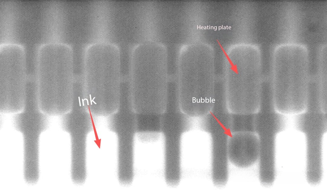
Two-Dimensional X-ray Imaging of Thermal Inkjet Printheads
II. Solutions
1. Physical Unblocking
After removing the printhead, soak it in warm water to soften residues, then use a fine brush to clean the internal channels.
Compressed air may be directed at the nozzle openings to remove blockages (air pressure must be controlled to avoid damage).
2. Chemical Cleaning
Dilute a specialized cleaning agent and soak the printhead for 30 minutes to dissolve oil or chemical residues. Protective gloves should be worn and proper ventilation ensured.
3. Preventive Measures
After use, flush the pipelines with clean water immediately and check the filters regularly.
Avoid mixing raw materials from different brands to prevent chemical reactions that may cause clogging.
4. Ink and Equipment Adjustment
Replace the ink with one that has better defoaming performance, or add a specialized defoaming agent.
Check the sealing of the negative pressure system to ensure stable pressure (for example, repair any air leakage points).
5. Standardized Operation
Regularly perform printhead cleaning procedures, using compressed air or specialized cleaning liquid to remove bubbles.
Ensure the printhead is installed vertically to prevent bubble retention.
6. Emergency Handling
For minor air blockage, pressurized flushing (such as hydraulic flushing at twice the working pressure) or heating to soften bubbles may be attempted.
In cases of severe blockage, the printhead should be disassembled, and the filter or nozzle cleaned with a fine needle.
III. Precautions
When blockage is severe or the equipment is aging, replacing the printhead is recommended.
During operation, the power supply must be turned off to prevent liquid from contacting electrical circuits.
Thermal Inkjet (TIJ) Printhead Manufacturing Process
I. Core Technological Innovations
1. Intelligent Printhead Error-Correction Technology
Through real-time monitoring of the printhead status, clogged nozzles can be automatically detected and cleared using a heating flash-jet method. Combined with a detachable printhead design (which can be repaired by soaking in boiling water for 3–5 minutes), this significantly improves equipment stability.
New thin-film resistor materials (such as silicon nitride) extend the heater lifespan to three times that of traditional designs, reducing maintenance frequency.
2. High-Precision Droplet Control
Multi-grayscale jetting technology (VSDT) is used to achieve precise control of droplets as small as 5 pl, improving color transition smoothness by 40%.
The nozzle array density reaches 600 npi, supporting 720 × 1440 dpi high-resolution output to meet the requirements of industrial barcode printing.
II. Expansion of Industrial Applications
1. Packaging Printing
In food packaging coding applications, printing speeds of 0.1 seconds per character can be achieved. Abrasion resistance meets the ASTM D5264 standard.
2. Consumer Electronics Manufacturing
Used for PCB board marking, with high-temperature-resistant ink formulations capable of withstanding 260°C reflow soldering, certified under IPC-610G standards.
III. Technology Comparison and Trends
| Feature | Thermal Inkjet (TIJ) | Micro Piezo (e.g., PrecisionCore) |
| Printing Speed | Faster (high printhead integration) | Slower but more stable |
| Color Performance | Smooth color transitions | Precise control |
| Cost | Low (cartridge-based design) | High (long printhead lifespan) |
| Application Scenario | Large-scale industrial printing | High-precision photography / industrial-grade |
Current technology is developing toward environmentally friendly inks (such as water-based UV-curable inks) and ultra-high-speed array printheads (100,000 drops per second).
IV. Face Shooting Technology
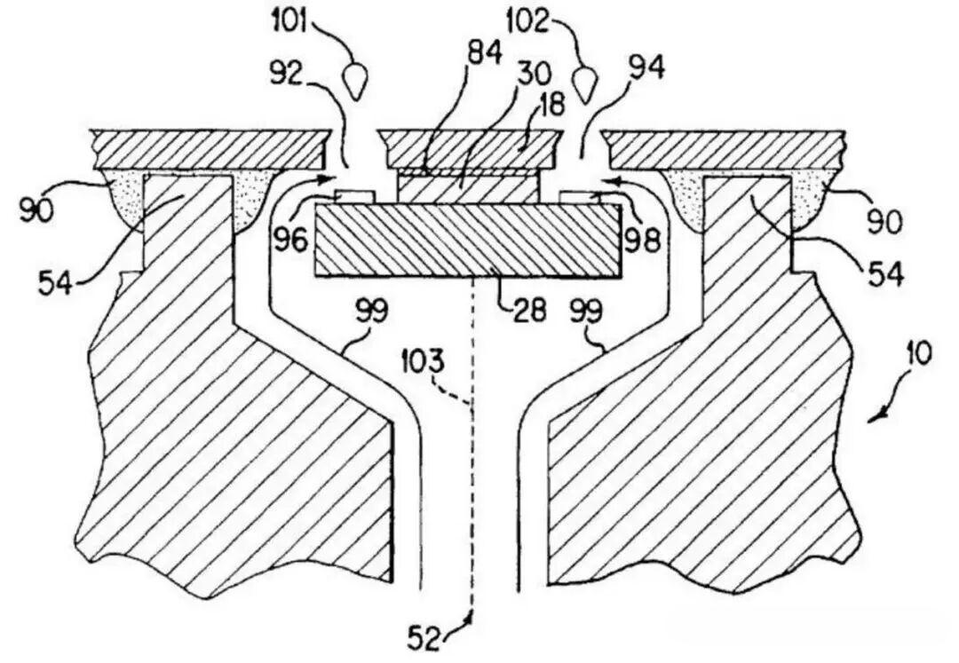
This technology integrates actuator arrays along the edge of the chip, enabling vertical control of droplet ejection relative to the substrate surface, with an error of less than ±3 μm, improving precision by 40% compared to previous side-shooting technology.
The actuators are manufactured using MEMS processes, integrating over 3,000 heating elements on a single chip, with response times reduced to 5 μs.
V. Imageable Barrier Layer
A three-dimensional structure is formed through layered photoresist exposure using photolithography. This structure functions both as an ink manifold (flow channel width 50 μm) and a heating chamber (volume 1.5 nL), reducing the fluid path length by 60%.
The material used is high-temperature-resistant polyimide (PI-2615), capable of withstanding instantaneous heating cycles up to 300°C.
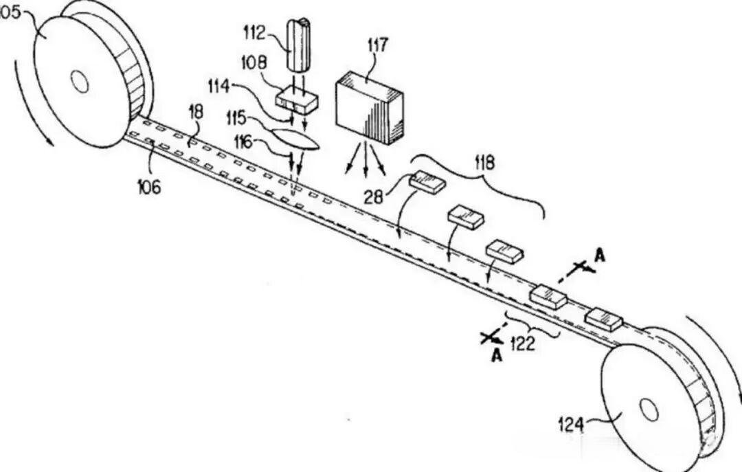
VI. Key Manufacturing Processes
| Process Step | Technical Parameters | Innovation |
| Laser nozzle etching | 355 nm UV laser, aperture 25 ±1 μm | Direct forming on polyimide circuit boards |
| Automated assembly | Vision positioning accuracy ±2 μm, yield rate 99.99% | Six-axis robotic mounting system |
| Testing and calibration | Online jetting frequency detection (20 kHz sampling) | AI dynamic compensation for droplet volume deviation |
VII. Performance Advantages
Production Efficiency
A single production line can achieve a daily capacity of 120,000 units, which is three times higher than TIJ 1.5 technology.
Reliability
Complies with JEDEC JESD22-A108 standards, with a lifespan of up to 1.5 billion jetting cycles.
Cost Control
Material utilization has increased to 92%, reducing the cost per chip by 28%.