
Analysis of the Relationship Between Print Quality and Substrate
The surface characteristics of the substrate (printing material) directly determine wetting behavior and dot formation during the printing process, thereby affecting the final output quality. The analysis can be conducted from the following aspects:
Influence of Substrate Surface Properties on Wetting Angle and Dot Diameter
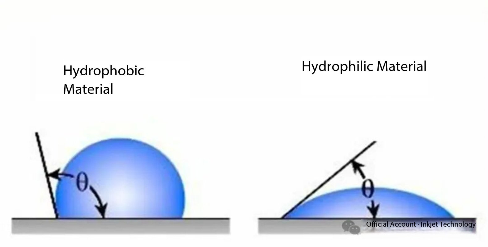
- The wettability of a substrate is characterized by the contact angle θ (a smaller θ indicates better wettability). Surface roughness is a key factor:
- When the intrinsic contact angle is less than 90°, increasing surface roughness reduces θ, promotes liquid spreading, and results in larger and more uniform dots.
- Conversely, when θ is greater than 90°, increased roughness enhances hydrophobicity, inhibits ink spreading, and leads to smaller, potentially non-uniform dot diameters.
- Other properties, such as surface energy and chemical characteristics, also modulate dot size:
- High-surface-energy substrates (e.g., polar materials) reduce θ and improve wettability.
- When the polarity of the liquid and the solid is similar, interfacial tension is reduced, further enhancing wetting.
- Substrates with good wettability can form larger and more stable dots, improving ink coverage and print resolution.
Effect of Surface Smoothness on Color Strength
- Smooth substrates (such as polished paper or films) provide a uniform contact interface. With a reduced contact angle (θ < 90° for hydrophilic surfaces), ink spreads more completely, resulting in higher color saturation and consistent color strength.
- Rough surfaces (such as textured textiles), on the other hand, tend to exhibit an increased apparent contact angle (θ > 90° for hydrophobic behavior). Ink penetration becomes uneven, leading to inconsistent color strength or whitening effects.
- Environmental factors also play a role: elevated temperature can reduce surface tension and indirectly improve wettability, whereas contamination (e.g., oil residues) increases θ and weakens color strength.
Influence of Substrate Dimensional Stability on Dot Position Accuracy
- Dimensionally unstable substrates (such as stretchable textiles or paper prone to expansion and contraction) may deform during printing, causing dot displacement and degrading image alignment and sharpness.
- Dimensionally stable substrates (such as rigid plastics) maintain fixed dot spacing, ensuring geometric accuracy of printed patterns.
- Temperature variations can exacerbate dimensional instability—high temperatures cause expansion and low temperatures cause shrinkage—thereby indirectly disturbing dot positioning through changes in surface tension.
Optimization Recommendations
- For high-roughness substrates, surface pretreatments (e.g., plasma activation to increase surface energy) are recommended to achieve balanced wettability and controlled dot size.
- For dimension-sensitive applications (such as precision printing), materials with low thermal expansion and shrinkage should be selected, and environmental temperature and humidity should be tightly controlled.
Xaar Printhead Variable Dot Technology Analysis
- Pulse operation at higher frequencies
- Up to seven micro-drops per pixel
- Droplets merge outside the nozzle plate before full drop formation
- Smaller droplets require shorter channels and smaller nozzles to reduce acoustic path length
- Increased heat generation

1. High-Frequency Pulse Driving Principle
1.1 Basic Parameter Configuration
- Operating frequency range: 18–36 kHz (corresponding to the upper limit of human audible sound)
- Maximum droplets per pixel: 7 drops (minimum volume per drop: 3.5 pL)
- Pulse interval: 2.8 μs (corresponding to the propagation time of sound at 340 m/s in a 100 μm channel)
1.2 Timing Control Strategy
Typical drive waveform generation logic:
def generate_waveform(drop_count):
base_voltage = 24 V # Reference drive voltage
for i in range(drop_count):
apply_pulse(width=1.2 μs, amplitude=base_voltage + i*3 V)
delay(2.8 μs) # Ensures phase alignment of acoustic wave superposition
2. Droplet Coalescence Dynamics
2.1 Channel Optimization Design
| Parameter | Typical Value | Technical Function |
| Nozzle diameter | 16 μm | Reduces the Weber number below 0.7 |
| Channel length | 80 μm | Shortens acoustic transmission time by 40% |
| External plate distance | 50 μm | Provides controlled space for droplet coalescence |
2.2 Multiphysics Coupling Effects
- Thermal effects: Continuous pulsing reduces ink viscosity by 12% (Δη/°C = −0.15 mPa·s)
- Acoustic superposition: Constructive interference occurs after the third pulse, increasing pressure amplitude by 2.1×
- Fluid interface dynamics: Surface tension work during coalescence is approximately 0.8 nJ
3. Key Technological Breakthroughs
3.1 Micro-Droplet Sequence Control
- Time–voltage hybrid modulation technique:
- Leading pulse: 22 V / 1.0 μs to initiate nucleation
- Main pulse sequence: 18–30 V / 0.8 μs for incremental volume control
- Damping pulse: −5 V / 1.5 μs to suppress residual oscillation
3.2 Thermal Management Solutions
- Integrated micro thermoelectric cooler (TEC):
- Cooling rate: 15 °C/ms
- Temperature stability: ±0.3 °C
- Ink circulation system flow rate: 8 μL/min
4. Performance Metrics Comparison
| Droplet Count | Volume (pL) | Positioning Accuracy (μm) | Grayscale Levels |
| 1 | 3.5 | ±2.1 | 16 |
| 3 | 10.5 | ±3.7 | 64 |
| 5 | 17.5 | ±5.2 | 160 |
| 7 | 24.5 | ±6.8 | 256 |
5. Failure Mode Analysis
- Satellite droplet formation: Probability increases to 23% when pulse interval exceeds 3.2 μs
- Thermal accumulation effect: Droplet volume drift reaches 4.7% after 30 minutes of continuous operation
- Cross-talk interference: An 8% jetting deflection occurs when the adjacent nozzle spacing is less than 60 μm
Analysis of Circuit Integration Technology in HP Thermal Inkjet (TIJ) 2.0
1. Technical Architecture and Innovations
Integrated Printhead Matrix Design
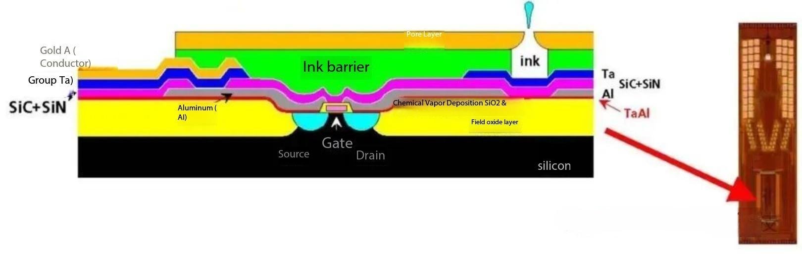
- Silicon-based CMOS processes are used to monolithically integrate heating elements, driver circuits, and nozzle arrays, enabling high-density routing (line width < 5 μm).
- 3D stacking technology reduces the number of interconnect layers and lowers signal latency (measured latency reduction of ~40%).
External Interface Optimization
- The MIPI (Mobile Industry Processor Interface) protocol replaces traditional parallel buses, reducing pin count from 64 to 12.
- Case example: HP PageWide TIJ 2.0 printheads use an integrated ASIC (Application-Specific Integrated Circuit) to drive 3,840 nozzles on a single chip.
2. Performance Advantages
Improved Reliability
- Integrated temperature sensors and feedback circuits dynamically regulate heating power, extending nozzle lifetime to approximately 10 billion firing cycles.
Reduced Power Consumption
- Dynamic voltage regulation lowers standby power to below 1 W, a 60% reduction compared with previous-generation TIJ technology.
3. Application Scenarios
Industrial High-Speed Printing
- Supports resolutions up to 1200 dpi × 1200 dpi, suitable for variable data printing (VDP) in pharmaceutical packaging.
Flexible Electronics Integration
- Can be embedded into smart label circuitry, enabling integration of RFID and printing functions on a single platform.
4. Technical Challenges
Thermal Management
- High integration density results in localized heat fluxes up to 10⁶ W/m², requiring microfluidic cooling channel designs.
Cost Control
- Wafer-level packaging (WLP) yields below 80% currently limit large-scale mass production.
Comparison with Conventional TIJ Technology
| Parameter | Conventional TIJ | HP TIJ 2.0 |
| Drive Method | External FPGA | Integrated ASIC |
| Nozzle Density | 600 dpi | 1200 dpi |
| Interconnect Complexity | High (multiple PCB layers) | Low (single-chip design) |