
Epson I1600 High Drop Printing Waveform Adjustment Key Considerations
1. Core Optimization of Droplet Kinetic Energy Enhancement
Speed Classification Improvement Strategy:
- Drop height and speed matching formula: Based on the classic printing distance of 0.5-2mm corresponding to 8±0.5m/s as the baseline, high drop scenarios require increasing the droplet speed according to the formula: V_target = 8 + 1.2 × (H-2) (H is the drop height in mm). For example, a 5mm drop height would require the speed to be increased to over 11.6m/s to prevent drop displacement caused by gravity.
- Voltage and speed linkage: Enhance kinetic energy by adding bipolar pulses. Increase the main pulse voltage by 5-8V (but keep it ≤42V as a safe upper limit), and raise the pre-pulse amplitude from 60% to 80% of the main pulse to create a “dual-drive” pressure field that enhances initial ejection force.
Pulse Timing Precision Control:
- Shorten the pre-pulse to main pulse interval: From the conventional 2.5μs, compress it to 1.8-2.0μs to utilize the pulse superposition effect to strengthen the pressure peak inside the flow channel, making the droplet acceleration stage more focused.
- Extend main pulse holding time: For every 1mm increase in drop height, extend the holding time by 2μs (e.g., for a 3mm drop height, the holding time extends from 35μs to 39μs), ensuring that the piezoelectric element deforms sufficiently to push the required amount of ink for continuous kinetic energy.
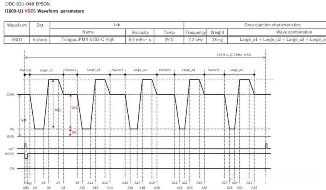
2. Waveform Compensation Plan for Trajectory Stability
Self-Elimination of Satellite Droplets Waveform Design:
- Enable the “main pulse + damping double pulse” structure: Add the first damping pulse 1.2μs after the main pulse (amplitude is 30% of the main pulse, width 1.5μs), then apply a second negative damping pulse (−12 to −15V) with a 0.8μs interval. This pressure wave interference eliminates satellite droplets at high speeds, ensuring that the main droplet ratio is ≥97%.
- Surface Tension Adaptation Adjustment: If the ink surface tension is <28mN/m, reduce the second damping pulse amplitude by 1-2V to prevent excessive disturbance that could cause the liquid meniscus to break.
Gravity and Air Resistance Compensation:
- Ink Droplet Volume Adaptation: Preferably use 6.2pl or 9.3pl large droplet modes (4-level grayscale), lock the corresponding pulse combination with the waveform, and utilize the inertia of larger droplets to resist air resistance.
- Frequency Adjustment: Lower the spraying frequency from the conventional 21.6kHz to 15-18kHz, extending the nozzle recovery time to avoid interference from high-frequency spraying, ensuring that each droplet’s trajectory remains stable.
3. Residual Vibration Suppression and Hardware Collaboration
Avoiding Resonance Between Waveforms and Structures:
- Dynamic Pulse Slope Adjustment: Monitor the rise slope of the waveform using an oscilloscope, reducing it from the conventional 8V/μs to 6-7V/μs to slow down the deformation speed of the piezoelectric element, reducing residual vibration amplitude in high drop scenarios (must be ≤0.3V peak).
- Frequency Resonance Point Shift: Avoid the common resonance range of 28kHz ±5%, and adjust the frequency to 16kHz or 24kHz based on drop height, breaking the resonance condition by offsetting the waveform timing (±0.2μs).
Environmental and Waveform Closed-loop Adaptation:
- Temperature and Humidity Compensation Enhancement: For each temperature fluctuation of ±3°C, adjust the voltage compensation coefficient from the conventional -0.35V/°C to -0.5V/°C, updating the formula to V_actual = V_set – 0.5 × (T-25) to offset the increase in ink viscosity caused by low temperatures.
- Low Humidity Protection: If the humidity is <40%, add a “pre-spray pulse” (amplitude 5V, width 1μs) to the waveform, inserting one pulse for every 10 print pulses to maintain nozzle moisture and stabilize the liquid meniscus.
4. Waveform Diagnosis for High Drop-Specific Faults
Fault Phenomenon: Waveform Problem Source & Solutions
- Scattered Drop Points: Inadequate droplet speed + interference from satellite droplets. Solution: Increase the main pulse voltage by 2-3V and add double damping pulses.
- Vertical Ghosting: Residual vibration causing drift in spray timing. Solution: Extend the pulse interval to 3μs and reduce the rise slope.
- Edge Blurring: Air resistance deforming the droplet. Solution: Switch to 9.3pl droplets and increase speed to 13m/s.
5. Operational Safety and Maintenance Enhancement
Voltage Adjustment Restrictions:
- The single voltage adjustment amplitude should be ≤±3V (conventional ±5V), with cumulative adjustments not exceeding 20% of the initial value, to prevent accelerated aging of piezoelectric elements due to sustained high load (life expectancy warning threshold reduced from 10.6 billion cycles to 8 billion cycles).
- After adjusting waveform parameters 3 times, use nozzle pattern checks to verify droplet speed uniformity (deviation ≤ 0.8m/s); otherwise, restore to previous parameters.
Maintenance Cycle Adaptation:
- For high drop printing, perform a deep cleaning and recalibrate the waveform every 50 hours (conventional is 100 hours), focusing on testing droplet speed decay. If the speed decreases by >1m/s, apply voltage adjustments according to the viscosity compensation formula.
Ricoh G5 Printhead Complete Guide to High Drop-Distance (10 mm) Waveform Adjustment & Critical Considerations
I. Core Parameter Adjustment Logic & Key Considerations
(Optimized for 8–10 mm drop-distance scenarios)
1. Pulse Width: Balancing Driving Force and Drop Integrity
- Adjustment Principle
High drop distances require increased initial droplet kinetic energy to overcome air resistance. Pulse width should be extended to 1.1–1.3× the baseline value (3.5 μs).
Drop-distance correlation formula:
t_fire = t_base × (1 + 0.06h)
where h is the drop distance in millimeters.
Example:
At a 5 mm drop distance, pulse width should be adjusted to 4.5–5.0 μs to ensure sufficient piezo deformation and strong ink ejection. - Prohibited Operation
Pulse width must not exceed 5.5 μs, even at a 10 mm drop distance. Excessive pulse duration can cause sustained chamber pressure, leading to ink backflow into the driver circuitry. - Verification Criteria
High-speed camera observation should confirm that droplet velocity at 1 mm from the nozzle reaches 8–12 m/s (significantly higher than the standard 6–8 m/s), with no visible deformation or breakup.
2. Voltage Amplitude: Dynamic Compensation for Velocity Loss
- Voltage Boost Strategy
Droplet velocity loss increases significantly at high drop distances. Driving voltage should be increased to 20–24 V (baseline: 18 V), following the formula:
V_peak = 20 + 0.5h
Example:
At an 8 mm drop distance, voltage should be raised to approximately 22 V to enhance piezo vibration amplitude via a stronger electric field. - Linked Optimization Rule
Voltage and pulse width must be tuned together.
For every 0.5 μs increase in pulse width, voltage can be reduced by ~0.6 V to avoid cumulative mechanical stress on the nozzle. - Safety Threshold
Voltage must be strictly limited to ≤30 V (Ricoh G5 absolute tolerance: 32 V).
During continuous printing, enforce a 5-minute cooldown per hour to prevent thermal overload and irreversible printhead damage.
3. Waveform Shape Optimization: Suppressing Satellites & Residual Vibration
- Multi-Pole Pulse Design
Adopt a three-pole waveform:- Positive main pulse
- Reverse suppression pulse
- Fine-tuning pulse
- The reverse pulse should be 50–60% of the main pulse voltage, with a duration of 1.0–1.5 μs.
The fine-tuning pulse should be 5–8 V.
This configuration can reduce satellite droplets by over 70%, effectively preventing droplet splitting at high velocities. - Rising/Falling Edge Control
- Extend rise time from 0.3 μs to 0.4–0.6 μs to soften pressure transients and avoid filamenting at the nozzle exit.
- Shorten fall time to 0.2–0.3 μs to rapidly cut off ink flow and prevent tailing.
- Pre-Pulse Configuration
Add a 0.8–1.2 μs pre-pulse before the main pulse at ~30% of the main voltage.
This pre-excites the ink channel, placing the ink in a “pre-accelerated” state and reducing velocity fluctuation at high drop distances.
4. Frequency & STB Parameter Matching: Avoiding Long-Distance Resonance
- Frequency Reduction Strategy
For high drop distances, reduce jetting frequency to 20–25 kHz (from the typical 28–33 kHz), using:
f = 30 − 1.2h
Example:
At 6 mm drop distance → 22.8 kHz
This prevents ink channel resonance that can cause velocity instability. - STB Extension
Total waveform period (STB) should be increased to 38–45 μs, ensuring the droplet fully separates from the nozzle before the next firing cycle and avoiding airflow interference between pulses. - Drop-Distance Tiering
- 3–5 mm: ~25 kHz
- 8–12 mm: 20–22 kHz + STB 42–45 μs
- This balances productivity with jetting stability.
_2026-02-02_20-44-14.png)
II. Pre-Adjustment Checks & Preparation
1. Environment & Ink Calibration
- Environmental Control (Stricter Than Standard)
- Temperature: 23–25 °C (±1 °C)
- Humidity: 55–65% RH
- Low humidity accelerates droplet evaporation and degrades jet quality—humidifiers are mandatory.
Compensation rule:
For every +1 °C, reduce voltage by 0.3 V and shorten pulse width by 0.1 μs. - Ink Property Verification
In addition to viscosity (8–12 cP) and surface tension (>32 mN/m), ink density must be verified (1.05–1.15 g/cm³).
Low-density inks are more susceptible to airflow deviation and should be replaced with higher-solids batches.
2. Hardware Condition Confirmation
- Nozzle Sealing Integrity Test
Use a pressure test: raise ink system pressure to 0.2 MPa and hold for 10 minutes.
No visible seepage at the nozzle face is acceptable—otherwise, replace sealing components. - Ink Supply Pressure Adjustment
Increase ink pressure to 0.15–0.20 MPa (standard: 0.08–0.12 MPa) to ensure continuous ink replenishment under high-speed ejection.
3. Tools & Parameter Backup
- Mandatory Tools
In addition to a dynamic droplet observation system:- Laser velocimeter (target velocity ≥5 m/s at impact)
- Airflow shielding device
- Standard tools are insufficient for high drop-distance tuning.
- Tiered Parameter Backup
Establish independent waveform profiles for:- 3–5 mm
- 6–8 mm
- 8–10 mm
- Each profile must include voltage, pulse width, and multi-pole parameters, clearly labeled “High Drop-Distance Only” and securely archived.

III. Adjustment Workflow & Risk Control
1. Step-by-Step Tuning Procedure (Five-Stage Method)
| Stage | Adjustment Focus | Test Method | Acceptance Criteria |
| 1 | Base pulse width | Fix voltage at 20 V, scan 4.0–5.5 μs | Velocity ≥8 m/s at 1 mm, no breakup |
| 2 | Drive voltage | Fix optimal pulse width, scan 20–24 V | Impact velocity ≥5 m/s, ≤1 satellite |
| 3 | Reverse pulse | Scan 0.8–1.6 μs | Residual vibration decay <1.5 μs |
| 4 | Frequency | Scan 20–25 kHz | Velocity CV <3%, no resonance |
| 5 | Drop-distance test | Print test strip at target distance | Impact deviation <0.15 mm, no ghosting |
2. Common Issues & Mitigation
- Dot Shift / Ghosting
Activate airflow shielding first. If unresolved, reduce frequency by 2 kHz and increase voltage by 0.5 V.
Avoid tuning in environments with airflow >0.5 m/s. - Satellite Droplet Instability
Increase reverse pulse voltage to 60% of the main pulse and extend duration by 0.2 μs.
Verify ink surface tension; replace ink immediately if <32 mN/m. - Rapid Velocity Decay
If impact velocity at 5 mm drop distance is <5 m/s, extend pulse width by 0.3 μs and increase voltage by 0.8 V, then verify ink pressure.
3. Safety & Maintenance Red Lines
- No Forced Operation Beyond Limits
Ricoh G5 design limit is 12 mm. Never force tuning beyond 10 mm during production—permanent printhead damage may result. - Post-Tuning Deep Maintenance
After each high drop-distance tuning session, flush the ink system three times with a dedicated cleaning fluid containing corrosion inhibitors to remove high-stress ink residues. - Periodic Velocity Re-Calibration
Every 5,000 m² of printing, re-measure velocity across all drop distances and update waveform parameters. Aging printheads exhibit gradual drive force degradation that must be compensated.