
Analysis of the Impact of Ink Droplet Angular Misfiring on Print Quality from a Microscopic Printhead Perspective
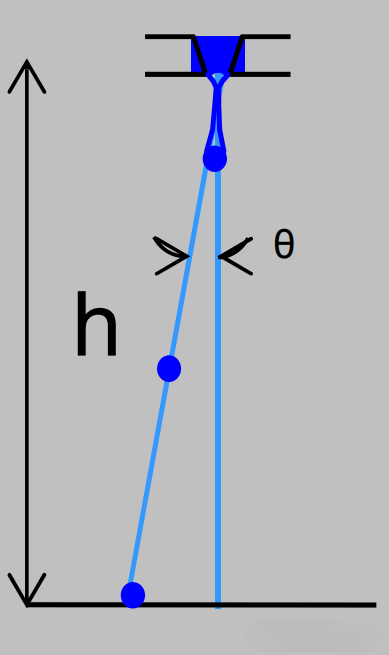
1. Microscopic Causes of Angular Misfiring
- Nozzle Geometric Deviation:
Deviation of the nozzle exit angle from the design specification (e.g., ±0.5°) causes the ink droplet flight path to shift, resulting in angular misfiring. - Meniscus Instability:
Imbalance of interfacial energy at the ink meniscus at the nozzle exit (e.g., contact angle > 90°) leads to abnormal droplet detachment direction. - Piezoelectric Drive Waveform Distortion:
Mismatch in the driving voltage waveform of piezoelectric printheads (e.g., excessively slow rising edge) can induce deviations in the droplet ejection angle.
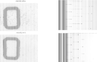
2. Direct Impact of Angular Misfiring on Print Quality
- Resolution Degradation:
Angular misfiring causes droplet landing position offsets (e.g., on the order of 10 μm), resulting in blurred edges or visible banding in images. - Abnormal Color Mixing:
In multi-color printheads, angular misfiring enlarges the overlap region between adjacent color droplets, leading to color shift or unintended color mixing. - Reduced Printhead Lifespan:
Prolonged angular misfiring accelerates nozzle wear, such as the propagation of microcracks in silicon carbide nozzles.
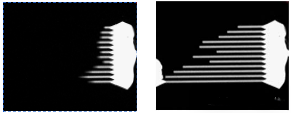
3. Microscopic Optimization Strategies
- Nozzle Material Enhancement:
Use high-precision silicon carbide ceramic nozzles (Mohs hardness ≥ 9) to minimize angular misfiring caused by mechanical deformation. - Flow Channel Design Optimization:
Stabilize the meniscus interfacial energy through microfluidic design (e.g., capillary channel dimensions < 50 μm). - Drive Waveform Calibration:
Precisely match the piezoelectric drive voltage waveform (e.g., PrecisionCore technology) to ensure vertical droplet ejection.
4. Technical Comparison
| Optimization Direction | Specific Measures | Performance Evaluation |
| Material Upgrade | Silicon carbide ceramic nozzles | Angular deviation reduced by 30% |
| Flow Channel Control | Microfluidic capillary design | Droplet trajectory stability improved by 50% |
| Waveform Matching | Dynamic adjustment of piezo drive waveform | Ejection accuracy up to ±1 μm |
5. Future Trends
- Intelligent Monitoring:
Integration of sensors to detect angular misfiring in real time and dynamically adjust drive parameters. - Multi-Material Compatibility:
Development of universal printheads compatible with UV and water-based inks to reduce angular misfiring caused by ink property variations.
Why a 180 LPI Encoder Can Print 720, 540, and Other DPI Values
First, let’s clarify the units:
- PPI (Pixels Per Inch) – Image resolution: the number of pixels contained within one inch.
- DPI (Dots Per Inch) – Device resolution: the number of physical dots a device can output within one inch.
- LPI (Lines Per Inch) – Screen/encoder resolution: the number of grid lines (or encoder lines) contained within one inch.
When the system outputs one ink drop for each complete encoder signal, a 180 LPI encoder can produce a 180 DPI image.
To understand how higher DPI values such as 360, 540, and 720 are achieved, let’s look at the working principle of the encoder sensor.
I. Signal Generation Principle
1. Encoder Structure Design
The main grating and the index (reference) grating have the same line pitch.
During installation, the two gratings are offset by 1/4 of a grating pitch (equivalent to 90° electrical phase), forming a quadrature relationship.
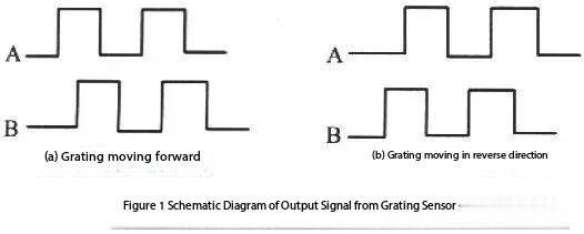
2. Moiré Fringe Conversion
As the gratings move relative to each other, the brightness variation of the moiré fringes is detected by photoelectric sensors and converted into two square-wave signals with a 90° phase difference, known as Phase A and Phase B.
II. Direction Detection Mechanism
(How the scanning system determines forward and reverse motion using the encoder)
1. Forward Movement
Phase A leads Phase B by 90°.
The signal sequence is:
00 → 10 → 11 → 01 → 00
The reversible counter performs incremental counting.
2. Reverse Movement
Phase B leads Phase A by 90°.
The signal sequence is:
00 → 01 → 11 → 10 → 00
The reversible counter performs decremental counting.
III. Quadrature (4×) Interpolation Technology
1. Signal Subdivision
By detecting four transitions per signal cycle (rising and falling edges of both A and B phases), the positional resolution is increased by a factor of four.
2. Implementation Methods
- Internal timers and counters in a microprocessor
- Dedicated reversible counter ICs
Since one signal cycle contains four distinct states:
00 → 10 → 11 → 01 → 00
the motion resolution can be further subdivided.
IV. DPI Expansion in the X Direction (Scan Direction)
Based on a 180 LPI encoder:
- 1 ink drop per 4 signal states → 180 DPI
- 2 ink drops per 4 signal states → 360 DPI
- 3 ink drops per 4 signal states → 540 DPI
- 4 ink drops per 4 signal states → 720 DPI
Summary
A 180 LPI encoder does not directly limit the printing resolution to 180 DPI.
By using quadrature signals, four-times interpolation, and controlled ink firing density, the system can achieve higher effective print resolutions such as 360 DPI, 540 DPI, and 720 DPI along the scanning direction.