
(Part 1): Image Processing
1. Image Data Processing
Image processing is performed according to the number of printable dot levels (gray levels) supported by the print head. Due to differences in manufacturing materials and working principles, print heads are divided into piezoelectric print heads and thermal bubble print heads. In general, piezoelectric print heads support variable dot printing, while thermal bubble print heads print in a single dot size.
1.1 Piezoelectric Print Heads
Let us first analyze how image data is processed when printed with piezoelectric print heads (such as Epson and Ricoh).
An image transitions from dark to light, and the color changes continuously. However, printing systems cannot output continuously variable dot sizes. Piezoelectric print heads are typically designed with four dot types: no dot, small dot (S), medium dot (M), and large dot (L).
Pixels in blank areas are rendered as no dots.
Pixels with ink coverage of 1–33% are rendered as small dots.
Pixels with ink coverage of 34–66% are rendered as medium dots.
Pixels with ink coverage of 67–100% are rendered as large dots.
Example: Original Image

Step 1: Image Preprocessing
The RIP software first converts the image into CMYK format
(printing uses four inks: Cyan, Magenta, Yellow, and Black).
Converted channel data:
| C Channel Data: | M Channel Data: |
 |  |
| Y Channel Data: | K Channel Data: |
 |  |
Step 2: The RIP Software Generates Dot Information
Based on the preset ink volume and dot-type mapping relationship (in real applications, tone curves and ICC profiles are added for better color reproduction), the RIP software generates the dot information.
Restored CMYK channel images after dot mapping:
| C Channel Data: | M Channel Data: |
 |  |
| Y Channel Data: | K Channel Data: |
 |  |
Zooming in on part of the K channel:
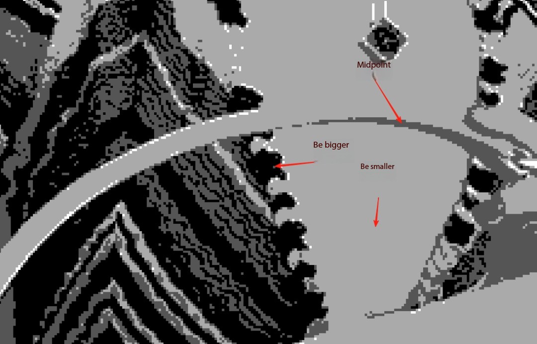
The image channel consists of three different density color blocks, corresponding to the following dot types:
Small Dot:
Medium Dot:
Large Dot:
After overlaying the four channels, the RIP produces the final image using the four dot types (small, medium, large, and none).
(Note: The RIP also uses tone curves and ICC algorithms to optimize reproduction; thermal bubble examples are shown later.)

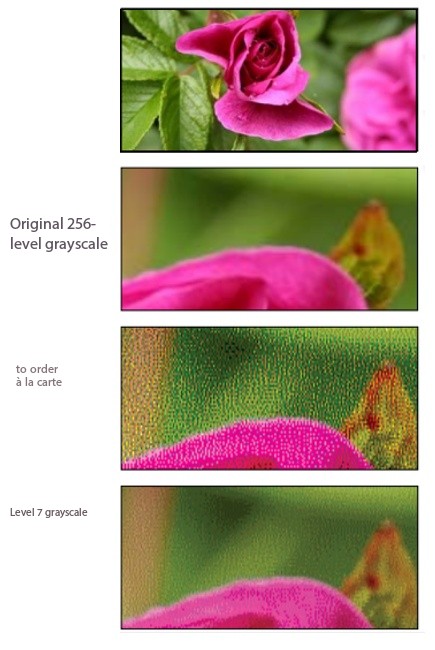
This describes the working process of a 4-level grayscale system.
In theory, the more grayscale levels, the better the reproduction.
However, due to material and engineering constraints, most products on the market support only 4 gray levels.
1.2 Thermal Bubble Print Heads
Working Principle:
Thermal bubble print heads heat a resistor inside the ink chamber. The rapid heating causes the ink to vaporize and form a bubble, which ejects the ink.
Therefore, thermal bubble print heads support only two dot levels: ink dot and no dot.
Pixels without color output no dots, while pixels with any ink coverage (1–100%) output a dot. The darkness of the color depends on ink density.
Using the same image, we analyze its workflow below:
Step 1: Image Preprocessing
The RIP software converts the image into CMYK format.
Converted channel data:
| C Channel Data: | M Channel Data: |
 |  |
| Y Channel Data: | K Channel Data: |
 |  |
Step 2: RIP Generates Dot Information (Without Tone Curve)
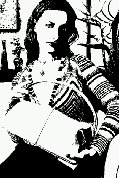
Restored CMYK channel images:
| C Channel Data: | M Channel Data: |
 |  |
| Y Channel Data: | K Channel Data: |
 |  |
Zooming in on the K channel:
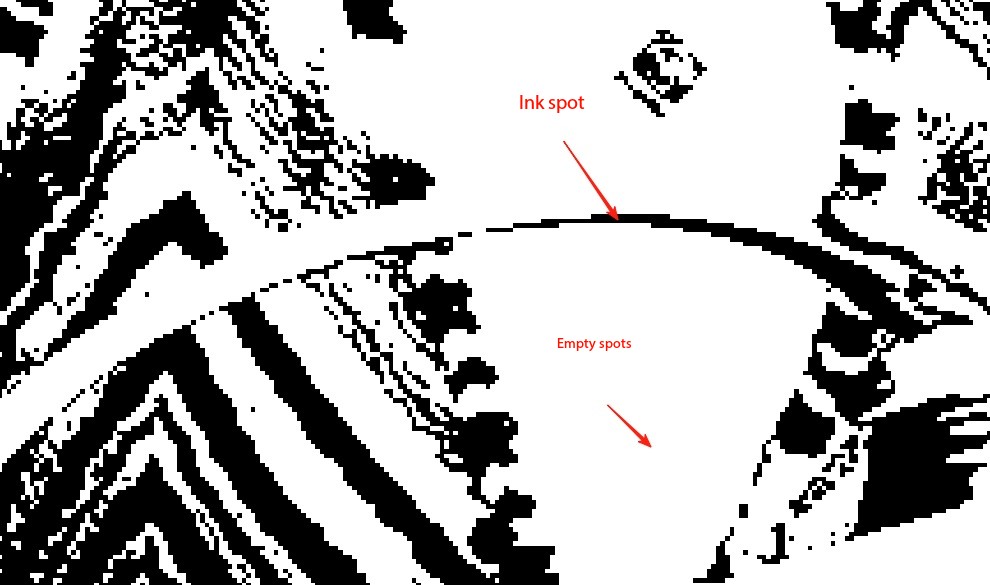
There are only two types of blocks in the channel:
No Dot:
Ink Dot:
Overlaying all four channels, the RIP produces the image using only two dot types (no dot and ink dot).
还原后如下:1.2.png)
RIP Generates Dot Information (With Tone Curve)
Restored CMYK channel images:
| C Channel Data: | M Channel Data: |
-1.2-C.png) | 1.2-M.png) |
| Y Channel Data: | K Channel Data: |
-1.2-Y.png) | 1.2-K.png) |
Overlaying the four channels produces the final tone-adjusted image:
还原后如下:1.2.2.png)
Conclusion
Tone curves are critical for image reproduction and optimization.
The tone curve directly affects the final printed image quality.
(Part 2): RIP Software
Functions of RIP Software
RIP (Raster Image Processor) refers to a pre-processing system for digital image output. When we need to print an image, the RIP software converts the image pixels from the computer into the dot (ink-droplet) information required for printing.
Common RIP software on the market includes RIIN, Maintop, Photoprint, Ultraprin etc.
Based on the number of dot levels supported by the printhead, the RIP software generates corresponding data.
1Bit Printing:
Dot level = 1
For blank pixels in the image, the PRN data is 0.
For pixels with color (ink amount 1–100%), the PRN data is 1.
2Bit Printing:
Dot level = 2
Blank pixels → PRN =00
Ink amount 1–33% → PRN =01 (Small dot)
Ink amount 34–66% → PRN =10 (Medium dot)
Ink amount 67–100% → PRN =11 (Large dot)
3Bit Printing:
Dot level = 3
Blank pixels → PRN =0000
Ink amount 1–14% → PRN =0001
Ink amount 15–28% → PRN =0010
Ink amount 29–42% → PRN =0011
Ink amount 43–57% → PRN =0100
Ink amount 58–71% → PRN =0101
Ink amount 72–85% → PRN =0110
Ink amount 86–100% → PRN =0111
Example — PRN Data Generated by a 1-Bit Printhead:
Color information:
1st row = K, 2nd row = C, 3rd row = M, 4th row = Y
PRN Data:
0 1 0 1 1 0 0 1
1 0 1 0 0 1 1 0
1 1 1 0 0 1 1 1
0 0 1 1 1 1 0 0
Most 1-bit printheads are thermal bubble printheads.
The printhead is internally driven, and the mainboard only outputs high/low pulses.
When the printing software sends PRN data to the mainboard, the mainboard converts the PRN instructions into high/low electrical signals that switch the nozzles on or off.
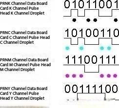
Example — PRN Data Generated by a 2-Bit Printhead:
Color information:
1st row = K, 2nd row = C, 3rd row = M, 4th row = Y
PRN Data:
01 10 00 11 10 01 00 10
00 11 00 10 01 01 11 11
11 10 10 11 11 10 10 00
10 10 11 00 10 10 00 11
Most 2-bit printheads are piezoelectric printheads.
These printheads are driven by power transistors on the mainboard.
The mainboard reads the PRN digital information.
It adjusts the corresponding waveform.
The waveform is converted into an analog signal through a DAC (Digital-to-Analog Converter).
The power transistor amplifies the signal to drive the printhead nozzles.

| PRNK channel data | 01 10 00 11 10 01 00 10 |
| Board K Channel Waveform | |
| Nozzle K Channel Ink Drop |  |
| PRNC channel data | 00 11 00 10 01 01 11 11 |
| Board C Channel Waveform | |
| Nozzle C Channel Ink Drop |  |
| PRNM channel data | 11 10 10 11 11 10 10 00 |
| Board M Channel Waveform | |
| Nozzle M Channel Ink Drop |  |
| PRNY channel data | 10 10 11 00 10 10 00 11 |
| Board Y Channel Waveform | |
| Nozzle Y Channel Ink Drop |  |
(Part 3): Driver Board
Driver Board
In a printing system, the driver board is responsible for converting image information processed by the software into signals that drive the printhead to eject ink onto the material and reproduce the image.
The printing system also includes additional peripheral functions, such as driving motors, turning UV lamps on/off, height detection, and paper sensing. These functions are auxiliary and not core functions of the driver board.
Below, we use a Single-Pass piezoelectric printhead system as an example to analyze the workflow of the driver board.
1. Workflow Process
- The upper-level software sends parameters to the driver board, including calibrated color values, encoder resolution, photodiode trigger delay distance, UV lamp delay distance, and the PRN file.
- After receiving this information, the driver board stores it in RAM.
The FPGA then retrieves these parameters and calculates the platform speed and material position based on the pulse feedback from the rotary encoder.
- When the material moves under the K nozzle row (assuming the material passes under K → C → M → Y nozzles), the printhead driver triggers the K printhead to eject the K-channel data from the PRN file according to the encoder pulses.
When the material reaches the C nozzle row, the C printhead ejects the C-channel data accordingly.
The M and Y channels follow the same logic.
- When the material moves under the UV lamp, the driver board sends a signal to turn on the UV lamp. After the material passes through, another signal is sent to turn off the lamp.
Next, we will focus on the encoder calculation method and printhead driving method.
Encoder Calculation Method
Scanning Mode
With a 180-line grating, the maximum resolution is:
180 × 4 = 720 DPI
Single-Pass Mode
With a 2500 P/R encoder wheel, one full revolution outputs:
2500 × 4 = 10,000 pulses
Example:
If a 2000 P/R encoder is required to output 1200 DPI, how should the wheel diameter be selected?
Wheel circumference:
10000 ÷ 1200 ≈ 8.3333 in
Convert to millimeters:
8.3333 × 25.4 = 211.6667 mm
Wheel diameter:
211.6667 ÷ π ≈ 67.38 mm
Principle of Quadrature (4×) Encoding
The grating encoder outputs two square-wave signals, A and B, with a 90-degree phase difference.
- Forward Movement
When A leads B by 90°, one cycle contains four state transitions:
00 → 10 → 11 → 01 → 00
Each transition counts +1, achieving 4× forward counting.
- Reverse Movement
When A lags behind B by 90°, the transitions are:
00 → 01 → 11 → 10 → 00
Each transition counts –1, achieving 4× reverse counting.
- Interference or Fault Condition
Irregular transitions cause the counter to ignore the signal and not count.
A state-transition diagram can be derived from these rules, where “+” represents +1 count, “–” represents −1, and “0” represents no action.
Printhead Driving Method
Waveform data stored or transmitted in the computer or driver board exists as discrete digital data.
However, when driving the printhead, the waveform must be a continuous analog voltage.
Therefore, a Digital-to-Analog Converter (DAC) is required to convert digital signals into analog voltage.
Common DAC chips include:
Epson E09A7218A digital-to-analog converter
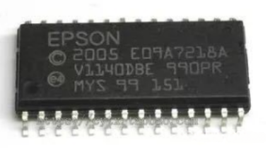
After the digital signal is converted to analog, it is applied to a power transistor (e.g., C4131 amplifier transistor) to drive the printhead to eject ink.
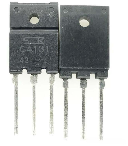
Example of Dot Formation
00 – Empty dot
01 – Small dot
10 – Medium dot
11 – Large dot
This shows the relationship between digital data → driver board → resulting ink droplet.
| PRNK channel data | 01 10 00 11 10 01 00 10 |
| Board K Channel Waveform | |
| Nozzle K Channel Ink Drop | |
| PRNC channel data | 00 11 00 10 01 01 11 11 |
| Board C Channel Waveform | |
| Nozzle C Channel Ink Drop | |
| PRNM channel data | 11 10 10 11 11 10 10 00 |
| Board M Channel Waveform | |
| Nozzle M Channel Ink Drop | |
| PRNY channel data | 10 10 11 00 10 10 00 11 |
| Board Y Channel Waveform | |
| Nozzle Y Channel Ink Drop | |
(Part 4): Printhead Workflow (Interpolation Principle)
Printhead Interpolation Principle
| EPSON I3200 Print Head | EPSON-I3200 Nozzle Arrangement: |
 |  |
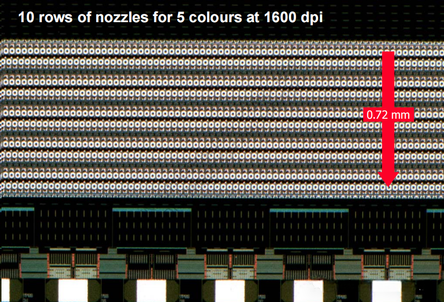
| HP Print Head | HP Print Head Nozzle Arrangement: |
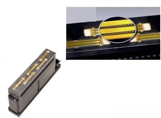 |  |
| Ricoh GEN5 Head | Ricoh GEN5 Head Nozzle Arrangement: |
 |  |
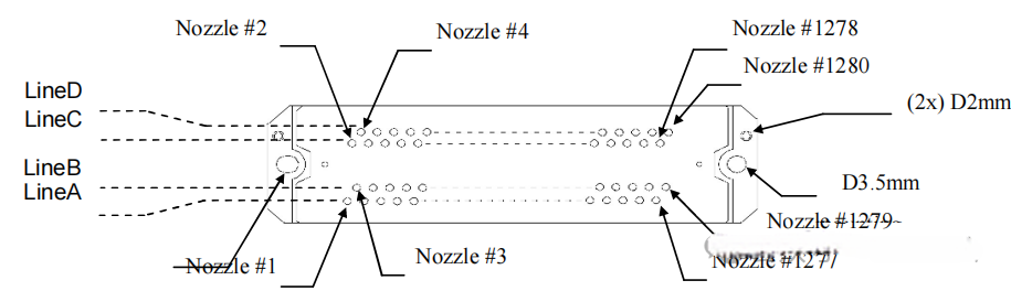
From the diagrams above, we can see that the two nozzle rows of each printhead are offset by exactly one nozzle.
(Ricoh G5 uses four-row interpolation; Brother printheads use six-row interpolation.)
Reasons for Interpolation Design
- Manufacturing limitations: It is not possible to arrange nozzles at the required density on a single straight line due to machining constraints.
- Inkjet interference reduction: Interpolation helps reduce ink disturbance between adjacent nozzles during ejection.
I3200-U1-E1-A1 Eight-Channel Four-Color Working Method
Each color uses two rows of channels, forming a two-row interpolation pattern.
Each row provides 300 DPI, and after interpolation, the result reaches 600 DPI.
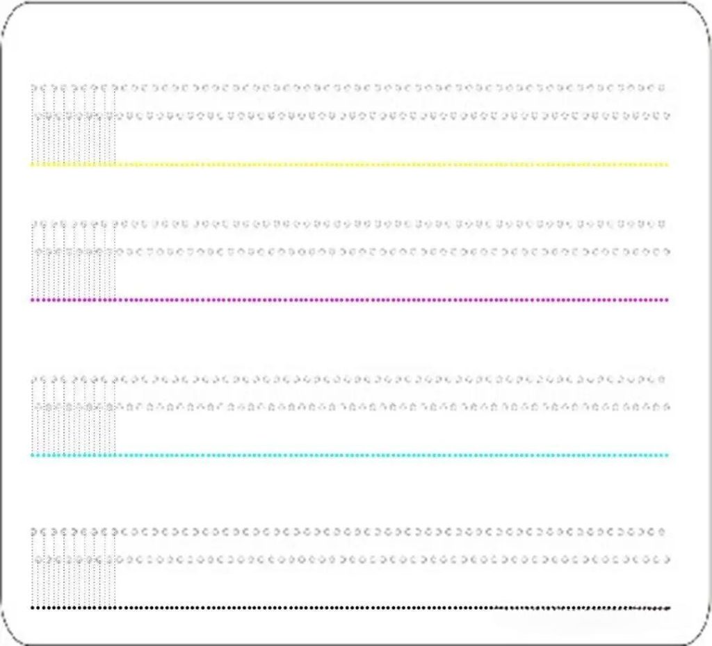
I3200(8)-A1HD: 8 Nozzle Rows / 8 Ink Inlets
Because the printhead has eight independent ink inlets, it can support 8 colors directly.(Alternatively, two inlets can feed the same color to achieve the U1-E1-A1 interpolation mode and reach 600 DPI.)
For example, using the following eight colors: K, C, M, Y, Lk, Lc, Lm, LLk
From the illustration, we can see that in this mode, adjacent colors are physically offset by one dot.

Ricoh G5 Four-Row Interpolation
Each row provides 150 DPI.
One printhead printing two colors → 300 DPI per color (adjacent colors offset by one dot)
One printhead printing one color → 600 DPI
Impact of Incorrect Interpolation Settings on Print Quality

Enlarged comparison of correct vs. incorrect interpolation

The comparison shows that when the software’s odd/even channel configuration does not match the physical printhead, significant artifacts appear in the final print.
In most software, the odd/even channel alignment can be configured in the color-registration (head calibration) settings.
| CH01 | CH02 | CH03 | CH04 | CH05 | CH06 | CH07 | CH08 |
| Y | Y | M | M | C | C | K | K |
| 0 | 1 | 0 | 1 | 0 | 1 | 0 | 1 |
| 0.000 | 0.190 | 0.952 | 1.143 | 1.905 | 2.095 | 2.857 | 3.027 |
| 0 | 9 | 45 | 54 | 90 | 99 | 135 | 143 |
Interpolation in Digital Inkjet Systems — Key Technical Notes
Interpolation is a critical technique that converts 2D graphic data into executable motion commands for the mechanical system. The algorithm discretizes continuous images into a dot matrix, and the dot-density directly affects print resolution.
In applications such as high-precision 3D color printing, the interpolation algorithm must balance color layering accuracy and synchronization between printhead movement and inkjet timing.
Incorrect parameters may cause line jitter, color misalignment, or banding.
Operational Guidelines
1. Parameter Configuration
Adjust the interpolation step size according to the device performance.
Recommended: ≤ 0.02 mm
Also, configure a proper acceleration curve to prevent sudden motion changes that may cause mechanical stress or print shift.
2. Synchronization Control
Interpolation frequency must dynamically match the printhead’s real-time status (ink level, temperature, etc.).
For example, in precision plotters, the laser positioning system must synchronize with printhead motion, keeping the error within ±0.01 mm.
3. Dynamic Optimization
Use real-time feedback to monitor line sharpness.
If lines appear blurry, reduce the interpolation step size and optimize the path-planning algorithm.
Maintenance Recommendations
Regularly check gear backlash in the transmission system (recommended ≤ 0.05 mm)
Use a laser interferometer to calibrate lead-screw accuracy
These steps can significantly reduce interpolation errors caused by mechanical deviations.