
G5 Printhead Ink Jetting at an Angle: A Complete Guide to Causes, Diagnosis, and Solutions
I. In-Depth Analysis of Root Causes
(1) Internal Printhead Clogging and Contamination (Most Common)
Mechanism:
The nozzle diameter of a G5 printhead is only several tens of microns. When impurities in the ink, dried crystallized ink, or fibers from cleaning wipes enter the nozzle, the originally round nozzle opening can deform into an oval or semi-circular shape, forcing ink droplets to deviate from their intended trajectory.
Typical causes:
a. Use of low-quality ink containing particulate impurities, or mixing inks from different brands, which may cause chemical reactions and precipitation;
b. Failure to properly seal the printhead after shutdown, allowing ink to evaporate and dry;
c. Debris from print media or airborne dust entering the nozzles.
(2) Environmental and Parameter Interference
- Static electricity:
In dry environments (humidity < 35%) or when static is generated by media friction, electrostatic charge can attract ink droplets and alter their flight path, while also drawing dust into the nozzles and worsening clogging. - Printhead distance and voltage abnormalities:
- If the distance between the printhead and the substrate exceeds 3 mm (recommended value), droplet kinetic energy decays, leading to trajectory deviation;
- Unstable or excessively high voltage in UV printers can interfere with printhead drive signals.
- Temperature and humidity imbalance:
- When ambient temperature falls below 20 °C, UV ink viscosity increases, raising jetting resistance;
- Humidity above 65% can cause moisture ingress into printhead circuitry.
(3) Mechanical Wear and Structural Deviation
- Component wear: Long-term use can reduce the precision of printhead support rails and drive motors, causing deviations in jetting angle.
- Assembly issues: Loose printhead installation, misalignment between nozzle and air cap, or aged sealing O-rings after disassembly and cleaning.
- End-of-life condition: The normal service life of a Ricoh G5 printhead is approximately 10,000–15,000 hours. Beyond this, nozzle wear and piezoelectric crystal degradation inevitably result in angled jetting.
(4) Software and Control System Errors
- Outdated firmware may cause command latency or loss of calibration parameters (e.g., incorrect bidirectional printing compensation).
- Modified or retrofitted equipment is prone to control board signal interference, leading to firing timing errors.
II. Step-by-Step Solution Strategy
Step 1: Basic Inspection and Environmental Optimization
- Status check:
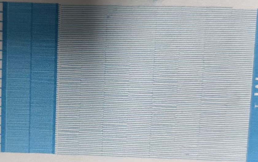
Print a nozzle test pattern. Saw-tooth edges, missing lines on one side, or fuzzy borders indicate angled jetting. - Environmental adjustments:
- Use ionizing air blowers to eliminate static electricity; ensure grounding resistance ≤ 10 Ω; maintain workshop humidity at 35–65%;
- Maintain room temperature at 25 °C ± 3 °C with air conditioning; avoid direct sunlight on the printhead.
- Parameter calibration:
- Use a feeler gauge to adjust printhead height to 3 mm (refer to the equipment manual) and ensure parallelism with the substrate;
- Check power stability and install a voltage stabilizer if necessary (220 V ± 5%).
Step 2: Printhead Cleaning and Unclogging
| Clogging Level | Cleaning Method | Key Operating Points |
| Mild clogging | Automatic cleaning | Run the machine’s “printhead cleaning” cycle 2–3 times, with 5-minute intervals |
| Moderate clogging | Manual flushing | 1. Power off and remove the printhead; 2. Use dedicated cleaning fluid for positive-pressure flushing (≤ 0.3 MPa) until all nozzles eject evenly |
| Severe clogging | Ultrasonic cleaning | 1. Use a 40–80 kHz ultrasonic cleaner with dedicated cleaning fluid (liquid level only 0.5 cm above the nozzle); 2. Clean for 2–5 min, soak for 30 min and repeat if needed; low-frequency units (≤ 28 kHz) are prohibited; 3. Air-dry, reinstall, and perform nozzle calibration |
Step 3: Mechanical and Software Calibration
- Mechanical calibration:
- Check lubrication of the printhead rail and apply appropriate lubricant; replace worn timing belts or motor bearings;
- Reinstall the printhead, ensuring concentric alignment between the air cap and nozzle; tighten mounting screws to the specified torque.
- Software calibration:
- Update firmware to the latest version and re-run “printhead alignment” and “color calibration” procedures;
- For modified machines, inspect control board wiring and replace damaged signal modules if necessary.
Step 4: Component Replacement and Final Measures
- Consumable replacement:
If angled jetting persists after cleaning, replace printhead sealing O-rings and ink filters (recommended every 3 months). - Printhead replacement:
a. Confirm end-of-life (total print volume > 15,000 m² or usage > 18 months);
b. Purchase an original Ricoh G5 printhead (avoid third-party compatibles) and perform full calibration after installation.
III. Preventive Maintenance Best Practices
- Routine care:
Run the “moisturizing” or capping procedure after daily shutdown; cover nozzles with dedicated moisturizing pads; perform deep cleaning once per week. - Consumables management:
Use only UV inks certified by the equipment manufacturer; do not mix brands; consume opened ink within one month. - Regular inspections:
Inspect mechanical wear, electrical connections, and grounding status monthly; maintain a detailed maintenance log.
This systematic approach can effectively diagnose and resolve angled jetting issues in G5 printheads while significantly reducing recurrence through proper preventive maintenance.
Effects of Pull and Push Waveform Phases on Droplet Quality and Velocity in Ricoh G5 & G6 Printheads
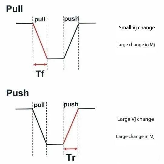
Ricoh G5 and G6 printheads control droplet formation through piezoelectric drive waveforms. The configuration of the Pull (contraction phase) and Push (ejection phase) directly affects droplet formation, velocity, and overall printing stability. The main mechanisms are explained below.
I. Control of Droplet Velocity by Waveform Phases
Role of the Pull Phase
During the Pull phase, the piezoelectric actuator contracts, creating negative pressure in the nozzle chamber to draw ink and prepare it for ejection.
- If the Pull voltage is too low, the initial droplet velocity is insufficient, increasing velocity loss during flight.
- Properly optimized Pull voltage increases the initial droplet velocity (typically 6–7 m/s measured 1 mm from the nozzle) and reduces landing-point deviation caused by airflow disturbances.
Dynamic Impact of the Push Phase
In the Push phase, expansion of the piezoelectric actuator generates a positive pressure wave that directly determines droplet acceleration and final ejection velocity. Test results show that:
- Increasing Push voltage (e.g., from 16 V to 17 V) can raise droplet flight height by about 15%, but exceeding 17.5 V significantly increases the risk of ink break or misfiring.
- At high firing frequencies (5–7.5 kHz), Push voltage must be increased accordingly to maintain sufficient ejection force; otherwise, droplet velocity decay intensifies, reducing printing efficiency.

II. Optimization of Droplet Quality Through Waveform Adjustment
Suppression of Satellite Droplets
Improper timing between Pull and Push phases (such as insufficient Pull strength or delayed Push pulses) can cause the droplet tail to separate from the main droplet, forming satellite droplets and resulting in print artifacts.
- A dual-pulse waveform (Pull preparation immediately followed by Push ejection, with an interval of approximately 2 μs) forces single-droplet formation and ensures accurate vertical droplet trajectories.
Stability of Droplet Size
- If the Pull phase is too short or the voltage is unstable, negative pressure in the ink chamber is insufficient, leading to increased droplet volume fluctuation—especially during grayscale transitions in the 7–21 pL range.
- Push voltage must be matched to ink viscosity. For example, UV inks often require stepped voltages (e.g., 17 V for the first pulse to initiate ejection, followed by 16.2 V for stabilization) to avoid ink piling or uneven color patches.
III. Coordinated Optimization Strategy
| Parameter | Influence Range | Optimization Recommendation |
| Pull Voltage | Initial droplet velocity and consistency | Maintain 16–16.5 V during new printhead break-in; avoid low voltage that causes weak droplet flight |
| Push Voltage | Ejection acceleration and satellite formation | Limit peak to ≤17.2 V; during high-frequency operation, raise ink temperature to 43 ± 2 °C |
| Pulse Interval | Risk of droplet separation | Keep dual-pulse interval ≤2 μs and calibrate in real time using a droplet observation system |
Note: Achieving the optimal balance between droplet quality and velocity requires dynamic calibration. For high-frequency, fine-detail printing, shortening the Push pulse width can increase speed, but the voltage must be reduced accordingly to prevent printhead overheating during sustained high-frequency operation.