
Key Considerations for Waveform Adjustment of Toshiba (TTEC) CE4M Printheads
Below is a consolidated set of key precautions and best practices for waveform adjustment of the TTEC CE4M printhead, organized in accordance with industrial control standards and precision inkjet technology requirements:
CE4M喷头_2026-01-05_12-45-03.jpg)
I. Basic Parameter Configuration
1. Selection of the Initial Waveform
It is recommended to start with the manufacturer’s default single-pulse waveform (e.g., 26 V amplitude, 2.18 μs pulse width) and then gradually fine-tune the rise and fall times.
2. Voltage and Frequency Matching
The driving voltage should be dynamically adjusted according to the ink type (UV or solvent-based).
- In winter, increase the voltage by 5–8% to compensate for higher ink viscosity at low temperatures.
- In summer, reduce the voltage by 3–5% to prevent misting and satellite droplets.
II. Environmental Adaptation Adjustments
1. Temperature Compensation Mechanism
Enable the printhead’s built-in temperature sensor.
- When ambient temperature drops below 10 °C, automatically extend the waveform rise time by 15%.
- Under high-temperature conditions, shorten the fall time by 10% to maintain stable jetting.
2. Humidity Control
Maintain the operating environment at 40–60% RH to avoid condensation, which may cause nozzle clogging or electrical short circuits.
III. Safety and Validation
1. Electrostatic Discharge (ESD) Protection
Before making adjustments, ensure the equipment grounding resistance is < 1 Ω to prevent dielectric breakdown of the piezoelectric elements.
2. Verification and Testing Standards
After waveform tuning, perform a full-gamut print test. The following criteria should be met:
- Color difference (ΔE) < 1.5
- Ink droplet landing deviation < 5%
IV. Maintenance Recommendations
1. Cleaning and Recalibration Cycle
Recalibration is required every 300 operating hours or whenever the ink batch is changed.
In winter conditions, it is recommended to shorten the interval to 200 hours.
2. Troubleshooting
If waveform distortion occurs, first check:
- Nozzle clogging rate (cleaning required if >5%)
- Ink supply system sealing integrity
This systematic approach ensures stable jetting performance, minimizes print defects, and extends the service life of the Toshiba TTEC CE4M printhead.
Complete Guide to Toshiba CF3R Waveform Adjustment for 20 mm Height-Difference Printing
I. Core Prerequisites: Technical Challenges of 20 mm Height Difference
The Toshiba CF3R printhead enables 20 mm height-difference printing through its high firing pressure and internal ink-recirculation design—far exceeding the typical 5 mm limit of conventional printheads.
However, a 20 mm droplet flight distance introduces significant challenges due to gravity and air resistance, including:
- Low-height regions (near the printhead): Excessive droplet velocity causes ink splashing
- High-height regions (far from the printhead): Velocity decay leads to dot misplacement and insufficient ink thickness
- Cross-height printing: Discontinuous grayscale transitions and uneven color density
Waveform tuning must dynamically compensate pulse parameters to balance these effects, while fully leveraging the CF3R’s 6-level grayscale capability (3–20 pL) to maintain fine image detail.
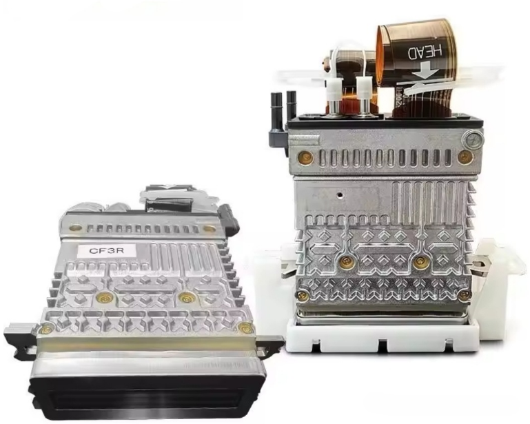
II. Core Waveform Parameter Adjustment Specifications
1. Baseline Pulse Calibration (Foundation for 20 mm Height Printing)
| Parameter | Standard Printing | Optimized for 20 mm Height | Adjustment Logic |
| Pulse Width | 1.8–2.2 μs | 2.3–2.6 μs (+0.2 μs for high-viscosity inks) | Extends droplet kinetic energy to offset velocity loss |
| Peak Voltage | 24–28 V | 29–32 V (≤34 V safety limit) | Compensates energy loss over extended flight distance |
| Rising-Edge Slope | 35–40 V/μs | 45–50 V/μs | Faster piezo deformation delivers higher initial velocity |
Target Condition
- Droplet velocity difference ≤ 0.5 m/s
- Recommended velocity range: 5.5–6.0 m/s
Forbidden Limits
- Voltage > 34 V → nozzle wear
- Pulse width > 2.8 μs → satellite droplets
2. Height-Segmented Dynamic Compensation Strategy (Critical Core)
Based on the patented “Structural Height-Difference Waveform Adjustment Method”, waveform parameters must be segmented by height, combined with CF3R Fine-Tuning single-nozzle calibration:
| Height Zone | Waveform Adjustment | Grayscale Allocation (6-level) | Application |
| 0–5 mm (Low) | Pulse −0.1 μs, Voltage −1 V | 3–8 pL small droplets | Root details of raised structures |
| 5–15 mm (Mid) | Baseline (2.4 μs + 30 V) | 8–15 pL medium droplets | Main image areas |
| 15–20 mm (High) | Pulse +0.2 μs, Voltage +2 V + pre-pulse | 15–20 pL large droplets | Top-surface filling |
Key Operational Points
- Create a Height–Waveform Mapping Table in machine software for real-time invocation
- Add a 1.2 μs pre-pulse in high zones to pre-pressurize the ink chamber and prevent large-drop delay
3. Ink Property-Specific Waveform Adaptation (Mandatory)
CF3R supports UV, solvent-based, and high-viscosity inks, but 20 mm printing requires tailored waveform tuning:
| Ink Type | Waveform Focus | Supporting Parameters |
| UV Ink | High surface tension (30–35 mN/m): extend falling edge to 1.1 μs | Increase recirculation to 30 mL/min to prevent curing at nozzle |
| High-Viscosity Ink (e.g., ceramic) | Pulse +0.3 μs, Voltage +3 V | Maintain ink temperature at 35–40 °C |
| Solvent Ink | Reduce voltage by 1–2 V to limit misting | Ambient humidity 40–50% |
III. Equipment Coordination & Environmental Control
1. Hardware Synchronization
- Printhead Height Calibration
Set initial height to 25 mm, referenced from the highest 20 mm structure, leaving a 5 mm safety margin. - Enhanced Cooling System
- Recommended firing frequency ≤ 8 kHz (below CF3R’s 9.2 kHz limit)
- Water-cooling flow: 8 L/min, temperature 22 ± 2 °C
- Negative Pressure Optimization
- Low zone: −3.5 mbar (anti-leakage)
- High zone: −5.0 mbar (improved ink supply)
2. Environment & Consumables Control
- Ambient temperature: 20–25 °C
- Airflow velocity: <0.3 m/s
- Ink filtration: 5 μm filters with internal circulation
- Nozzle maintenance: waveform calibration + cleaning every 1 hour
- Fine-Tuning correction required if nozzle offset > 0.1 mm
IV. Debugging Workflow & Troubleshooting
1. Standard Debugging Procedure (2–3 hours recommended)
- Baseline Validation: Flat substrate test using 2.4 μs + 30 V
- Height Simulation: Stair-step block (0–20 mm, 5 mm intervals)
- Dynamic Testing: Gradient printing; inspect transitions under magnification
- Stability Verification:
- Continuous printing: 30 min
- Printhead temperature ≤ 40 °C
- Velocity decay ≤ 5%
2. Common Issues & Solutions
| Issue | Waveform Cause | Solution |
| Blurred dots in high zone | Insufficient droplet energy (<5 m/s) | Voltage +1 V, Pulse +0.1 μs |
| Ink splashing in low zone | Excessive velocity (>6.5 m/s) | Voltage −2 V, falling edge → 1.0 μs |
| Grayscale banding | Parameter switching delay | Reduce step interval (1 set / 2 mm) |
| Precision loss over time | Thermal waveform drift | Frequency ↓ to 7 kHz, cooling ↑ to 10 L/min |
V. Safety & Maintenance Prohibitions
- Never adjust blindly without droplet observation equipment
(At 20 mm height, 0.1 μs or 1 V deviation causes severe defects) - High-viscosity inks must not exceed 32 V
(CF3R piezo breakdown limit: 35 V) - Waveform recalibration is mandatory after every ink change
- Single-nozzle Fine-Tuning must not be skipped
(20 mm height amplifies nozzle inconsistency;
1,278 nozzles must remain within ±0.05 mm deviation)