
I. Installation Adaptation and Hardware Compatibility Control
(1) Mechanical Installation Accuracy Assurance
1. Positioning and Distance Calibration
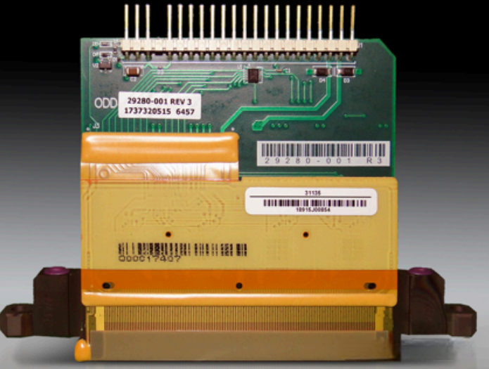
The Emerald series printhead adopts a high-precision nozzle array design. During installation, a micron-level adjustment platform (repeat positioning accuracy ≤0.01 mm) must be used to ensure the distance between the nozzle surface and the printing substrate is controlled within 1.2–2.0 mm.
The distance should be slightly adjusted according to ink type:
- Water-based ink: 1.5–2.0 mm
- UV ink: 1.2–1.8 mm
Parallelism deviation must be < 0.02 mm/m.
The mounting bracket should be made of rigid aluminum alloy (load capacity ≥3 kg), and shock-absorbing pads should be installed (thickness 2 mm, hardness Shore 70°) to reduce the impact of machine vibration on jetting accuracy.
2. Heat Dissipation and Protection Design
A heat dissipation clearance of ≥30 mm must be reserved on the side of the printhead.
The nozzle surface should be installed with a 1° downward tilt (±0.1°). This angle reduces the probability of UV ink curing residues and also lowers the risk of ink accumulation with eco-solvent inks.
For outdoor printing environments, an additional dust-proof protective cover should be installed (protection level IP54).
Moisture-absorbing cotton strips should be attached inside the cover (replaced every 24 hours) to prevent dust and moisture from entering the nozzle chamber.
(2) Electrical Connection Anti-Interference Specifications
1. Cable and Connector Compatibility
The driver signal cable must use original dual-layer shielded cables:
- Outer layer: tinned copper mesh
- Inner layer: aluminum foil
Cable length must not exceed 1.8 m.
Connectors should use gold-plated terminals with contact resistance <0.02Ω.
Cable routing must follow the “three-line separation principle”:
- Drive signal cables
- Power cables
- Detection cables
Each group must be laid separately with a spacing of ≥18 cm, and must be kept away from UV lamp power lines (≥45 cm) to prevent waveform distortion caused by high-frequency electromagnetic interference.
2. Grounding and Power Stability
The printhead driver board must use independent grounding:
- Ground resistance ≤1Ω
- Single-point grounding method
- Ground cable cross-section ≥4 mm²
It is strictly prohibited to share the same ground with high-interference equipment such as inverters or motors.
The power supply system must include:
- Isolation transformer (≥500 VA)
- Power filter
Input voltage fluctuation must be ≤±5%, and ripple coefficient <1%.
Unstable voltage can cause abnormal piezo crystal response, resulting in ink droplet volume deviations exceeding 6%.
(3) Ink Supply System Parameter Matching
| Adaptation Item | Water-Based Ink (Dye Type) | Eco-Solvent Ink | UV Ink (Flexible) | Verification Frequency |
| Ink supply pressure | 1.0–1.5 mbar (positive pressure) | -0.8 to -1.5 mbar (negative pressure) | 0.6–1.2 mbar (positive pressure) | Check every 2 hours |
| Ink path filtration accuracy | 5 μm nylon filter | 3 μm stainless steel filter | 2 μm titanium alloy filter | Water/solvent: replace every 24h; UV: replace every 12h |
| Ink circulation flow rate | 1.2–1.8 L/h | 1.0–1.5 L/h | 1.8–2.2 L/h | Monitor every 3 hours |
| Degassing vacuum | ≥-90 kPa | ≥-95 kPa | ≥-98 kPa | Verify before startup and after ink replacement |
II. Waveform Parameter Debugging and Ink Adaptation Strategy
(1) Basic Parameter Safety Baseline
1. Core Parameter Hierarchical Settings
Based on the high-precision characteristics of the Emerald series, the basic parameters should be set according to ink type:
- Drive voltage
- Water-based: 16–22 V
- Eco-solvent: 18–24 V
- UV: 17–23 V
Adjustment increment ≤0.5 V.
- Pulse width
- Water-based: 2.0–2.6 μs
- Eco-solvent: 1.8–2.4 μs
- UV: 2.1–2.7 μs
A 0.1 μs deviation may cause droplet volume fluctuation of ±3 pL.
- Jetting frequency: 5–30 kHz
(UV ink recommended ≤28 kHz to avoid incomplete curing at high frequency) - Rising slew rate
- Water-based: 32–40 V/μs
- Eco-solvent: 35–43 V/μs
- UV: 33–41 V/μs
2. Ink Characteristic Linked Adjustment
Waveform parameters must be adapted to the physical properties of different inks:
Low-viscosity water-based ink (2–4 cP)
Adopt wide pulse + low slew rate
- Pulse width: 2.4–2.6 μs
- Slew rate: 32–35 V/μs
- Circulation flow: 1.6–1.8 L/h
Prevents droplet splitting.
Medium-viscosity eco-solvent ink (4–7 cP)
Adopt standard pulse + medium slew rate
- Pulse width: 2.0–2.2 μs
- Slew rate: 38–40 V/μs
- Ink temperature maintained at 30°C (viscosity reduced to 4–5 cP)
Improves jetting stability.
High-viscosity UV ink (7–10 cP)
Adopt pre-pulse + main pulse
- Pre-pulse voltage: 25% of main pulse
- Pulse interval: 2.2 μs
- Main pulse width: 2.5–2.7 μs
Printhead chamber temperature must be maintained at 32 ±1°C.
A temperature fluctuation of ±1°C may change UV ink viscosity by 1–2 cP, which must be compensated by waveform parameters.
(2) Multi-Scenario Pulse Mode Adaptation
| Application Scenario | Pulse Combination | Key Parameter Settings | Frequency Range | Core Advantage |
| High-precision wide-format advertising | Main pulse + damping post-pulse | Post-pulse voltage = 25% of main pulse, duration 1.1 μs | 20–30 kHz | Edge sharpness increased 15%, satellite droplets reduced 80% |
| Packaging UV color printing | Pre-pulse + main pulse + tail pulse | Pre-pulse interval 2.2 μs, tail pulse voltage = 15% of main pulse | 15–25 kHz | Color uniformity increased 10%, stronger adhesion |
| Multi-material switching printing | Three-level voltage pulses | Voltage difference ≤3 V | 5–20 kHz | Switching response <1.5 s, no recalibration required |
III. Environmental Control and Full-Lifecycle Maintenance Standards
(1) Scenario-Based Environmental Parameter Control
1. Temperature, Humidity, and Cleanliness Requirements
Environmental parameters should be controlled based on ink type.
Water-based ink
- Temperature: 20–25°C (±1°C fluctuation)
- Humidity: 55–65%
Install an ultrasonic humidifier if humidity <55% to prevent ink from drying too quickly.
Eco-solvent ink
- Temperature: 19–24°C (±1°C fluctuation)
- Humidity: 45–55%
Install a forced ventilation system (air speed ≥0.8 m/s) to remove evaporating solvents.
UV ink
- Temperature: 22–26°C (±1°C fluctuation)
- Humidity: 48–58%
Equip a UV protective ventilation cover and maintain a ≥35 cm distance between UV lamps and printheads to avoid temperature rise affecting waveform stability.
General cleanliness requirement
- Cleanroom level: Class 500
- Particle concentration (>0.5 μm): <500 particles/ft³
- Monitoring frequency: every 8 hours
If exceeded, activate FFU filtration units.
(2) Differentiated Maintenance Procedures
1. Daily Maintenance (By Ink Type)
Startup procedure
Water-based / eco-solvent ink
- Execute ink path degassing + nozzle test (1.5 minutes)
- If abnormal nozzles >2%, perform automatic cleaning (spray 8 ml cleaning fluid)
UV ink
- Start preheating system (32°C for 8 minutes)
- Run UV-specific degassing program
Prevents curing agent sedimentation.
Shutdown procedure
Water-based ink
- Clean ink path with pure water
- Inject moisturizing fluid
- Install sealing cap (humidity maintained at 70%)
Eco-solvent ink
- Circulate special solvent twice
- Inject anti-drying fluid with anti-corrosion additives
UV ink
- Flush with UV-specific cleaning fluid (containing decuring agent)
- Inject protective fluid after cleaning
- Shutdown maintenance must be completed within 2 hours to prevent ink curing.
2. Deep Maintenance (Extending Service Life)
Perform a three-stage maintenance procedure weekly:
Stage 1: Surface Cleaning
Use lint-free cloth soaked in cleaning liquid and wipe along the nozzle direction.
Horizontal wiping is prohibited.
Stage 2: Internal Cleaning
Water-based / eco-solvent
- Ultrasonic cleaning: 38 kHz for 4 minutes
- Cleaning liquid temperature: 30°C
UV ink
- Heated cleaning + ultrasonic
- Cleaning liquid temperature: 35°C
- Ultrasonic frequency: 35 kHz
- Duration: 6 minutes
Stage 3: Performance Verification
Use a droplet observation system:
- Droplet velocity deviation ≤4%
- Volume deviation ≤2%
- 100% nozzle channel firing normally
IV. Troubleshooting and Durability Protection
(1) Typical Fault Handling
| Fault Phenomenon | Core Troubleshooting Steps | Solution |
| Water-based ink dropout | Check filter blockage; check ink pressure stability | Replace 5 μm filter + calibrate pressure to 1.2 mbar |
| Eco-solvent ink leakage | Check negative pressure; check sealing ring aging | Adjust pressure to -1.2 mbar + replace fluororubber seal |
| UV ink curing blockage | Check preheating temperature; verify cleaning fluid | Increase preheat to 35°C + flush with decuring cleaner |
| Channel accuracy deviation | Check waveform consistency; check grounding | Recalibrate grouped waveforms + reinforce single-point grounding (≤0.5Ω) |
(2) Prohibited Operations and Lifetime Protection
1. Parameter and Operation Restrictions
- Do not reuse waveform parameters across different ink types.
Ink paths must be emptied before switching ink (residual <0.2 ml). - Do not blow the nozzle with compressed air.
Use original negative pressure devices. - In eco-solvent printing, shutdown longer than 8 hours is prohibited.
A micro-jetting procedure must run every 4 hours (jet 0.5 ml ink) to prevent ink drying.
2. Long-Term Storage and Protection
If the machine is stopped for more than 5 days:
- Water-based ink → moisturizing fluid
- Eco-solvent ink → anti-drying agent
- UV ink → dedicated protective liquid
The storage liquid must be replenished once per week.
Transport and storage conditions
- Use original shockproof packaging (ISTA 3A level)
- Storage temperature: 15–25°C
- Humidity: 40–60%
- Avoid direct sunlight
- Keep away from strong magnetic fields (motors, transformers) to prevent piezo crystal magnetization.