
Ricoh G5 & G6 Printhead Complete Guide to Waveform Optimization for Low-Viscosity Inks and Key Precautions
I. Core Parameter Adjustment Logic & Critical Considerations
1. Pulse Width: The Key to Controlling Excessive Drop Elongation
Adjustment principle
Low-viscosity inks are prone to drop tailing when the squeeze time is too long. Therefore, the firing pulse width should be reduced to 70–90% of the baseline value (3.5 μs).
A dynamic calculation model can be applied:
tfire=tbase×(1−0.08(μ0−μ))t_{fire} = t_{base} \times \left(1 – 0.08(\mu_0 – \mu)\right)tfire=tbase×(1−0.08(μ0−μ))
Where:
- μ0\mu_0μ0 = reference viscosity (8 cP)
- μ\muμ = actual ink viscosity
For example, with 5 cP ink, the pulse width should be adjusted to 2.5–3.0 μs to prevent excessive expansion after droplet ejection.
Prohibited operation
Do not compress the pulse width below 2.0 μs. Even for low-viscosity inks, sufficient piezo deformation space must be maintained. Insufficient drive displacement will cause a sharp drop in droplet velocity and unstable jetting.
Verification criteria
Using a droplet observation system, confirm that:
- Droplets are spherical and well-formed
- No “umbrella-shaped” dispersion occurs at nozzle exit
- Droplet volume remains within ±5% of the Ricoh G5 nominal value
2. Voltage Amplitude: Balancing Jetting Force and Convergence
Voltage reduction strategy
Low-viscosity inks have low flow resistance. Driving voltage should be reduced to limit jetting impact, typically by 10–15%.
Example:
- Baseline 18 V → adjusted to 14–15.6 V
Reference model:
Vpeak=V0×(1−0.3×ln(μref/μ))V_{peak} = V_0 \times \left(1 – 0.3 \times \ln(\mu_{ref} / \mu)\right)Vpeak=V0×(1−0.3×ln(μref/μ))
Where μref=8\mu_{ref} = 8μref=8 cP. This prevents excessive voltage from causing misting and satellite drops.
Linked adjustment rule
Pulse width and voltage must be adjusted inversely.
For example, when pulse width is reduced by 0.3 μs, voltage should be reduced by approximately 0.8 V to avoid droplet velocity instability.
Safety threshold
The minimum voltage must not fall below 18 V. Excessively low voltage leads to delayed piezo response and may cause long-term “head sleep” faults. Always reserve at least 2 V of operating margin.
3. Waveform Shape & Timing: Suppressing Residual Vibration and Satellites
Rise/fall edge optimization
For low-viscosity inks, faster voltage transitions are required. Reduce the rising edge time from the standard 0.3 μs to 0.15–0.25 μs to enable rapid pressure release.
Tests show that when the rising edge is ≤ 0.2 μs, satellite droplet formation can be reduced by more than 60%.
Bipolar pulse implementation
A bipolar waveform (positive firing pulse + negative compensation pulse) is strongly recommended.
- Reverse pulse voltage: 40–50% of forward pulse
- Duration: 0.8–1.2 μs
This effectively suppresses residual ink-channel vibration and prevents secondary droplets caused by inertia in low-viscosity inks.
Tickling waveform prohibition
Low-viscosity inks already exhibit high mobility and do not require tickling.
If the T2 parameter is mistakenly set above 2 μs, continuous nozzle seepage may occur, resulting in ink blotting.
4. Frequency Adaptation: Stability and Throughput Optimization
Base frequency increase
Low-viscosity inks are less sensitive to ink-path resonance. The firing frequency may be increased to 28–33 kHz (near the Ricoh G5 upper limit), combined with a reduced STB parameter (28–32 μs) to increase dot density per unit time.
Resonance avoidance techniques
If velocity fluctuations occur in the 26–30 kHz range:
- Apply frequency offset of 0.5–1 kHz, or
- Fine-tune voltage by ±0.5 V
This avoids large frequency reductions that would impact productivity.
Grayscale printing adaptation
At low grayscale levels (10–30%), reduce frequency by 5–8 kHz to prevent droplet coalescence under small-pulse driving and to ensure smooth tonal transitions.
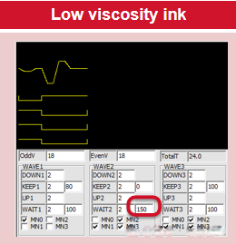
II. Pre-Adjustment Inspection and Preparation
1. Environment & Ink Calibration
- Maintain ambient temperature 22–26 °C and humidity 50–65%
- Low humidity (<45%) causes sharp surface tension reduction, increasing misting risk
- For every 1 °C temperature increase, reduce pulse width by 0.08 μs
- Perform viscosity–surface tension dual verification
- Viscosity: < 8 cP
- Surface tension: > 30 mN/m (ZnO-based ink reference)
If either parameter fails, replace the ink batch. Do not compensate through temperature forcing.
2. Hardware Condition Verification
- Nozzle sealing inspection
- Clean nozzle plate with anhydrous ethanol
- Let stand for 5 minutes
- Visible “tear-like” seepage indicates seal failure → replace gasket
- Reduce ink supply pressure to 0.08–0.12 MPa
Excess pressure causes continuous ink flooding and pre-jetting effects.
3. Parameter Backup & Tool Readiness
- In controller advanced mode, separately back up the low-viscosity waveform group, including voltage, pulse width, and bipolar pulse parameters.
- Prepare a dynamic droplet observation system (e.g., Optical Inkjet Analyzer). Key metrics:
- Droplet velocity: 6–8 m/s
- Satellite droplets: ≤ 1 per main droplet
Magnifying glasses are insufficient for accurate low-viscosity evaluation.
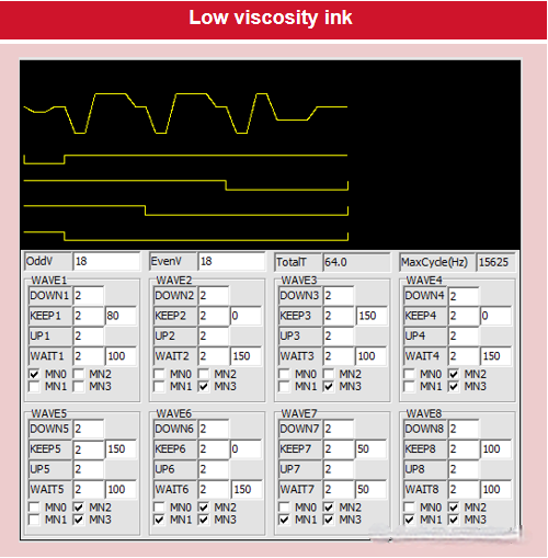
III. Debugging Workflow & Risk Control
1. Stepwise Tuning Method (Four-Stage Execution)
| Stage | Adjustment Target | Test Method | Acceptance Criteria |
| 1 | Pulse width | Fixed voltage 18 V, scan 2.5–3.5 μs | No tailing, volume deviation ≤ ±4% |
| 2 | Voltage amplitude | Fix optimal pulse width, scan 14–16 V | ≤1 satellite, dot deviation < 0.08 mm |
| 3 | Bipolar pulse | Fix forward pulse, scan reverse pulse 0.6–1.4 μs | Residual vibration decay < 2 μs |
| 4 | Frequency | Scan 28–33 kHz | Velocity CV < 2.5%, no resonance |
2. Common Issues and Mitigation Strategies
- Ink misting / diffusion spots
First reduce voltage by 0.8–1.2 V.
If ineffective, shorten rise time by 0.05 μs.
Avoid blindly reducing pulse width, which may cause density loss. - Seepage / pre-jetting
Immediately reduce ink pressure by 0.02 MPa and raise voltage floor by 1 V.
If unresolved, inspect nozzle sealing hardware. - Uneven grayscale
Enable multi-pulse stepped driving for grayscale below 50%.
Set small-pulse increments to 0.2 μs to prevent droplet merging.
3. Safety & Maintenance Red Lines
- Never tune without surface-tension verification
Inks below 28 mN/m will mist regardless of waveform optimization and may permanently contaminate the printhead. - Limit each tuning session to ≤20 minutes
Low-viscosity inks accumulate easily at the nozzle. Perform nozzle cleaning + idle jetting every 10 minutes. - End-of-day mandatory flushing
Flush ink paths with a low-viscosity-compatible cleaning fluid containing surfactants to prevent seepage caused by long-term ink stagnation.
Design Considerations for Large and Small Droplets in Ricoh G5 & G6 Printhead Waveforms
Ricoh G5 printheads precisely control the ejection behavior of large droplets (21 pL) and small droplets (7 pL) through waveform design. The core objective is to balance jetting stability and printing accuracy. Key design considerations are outlined below.
I. Waveform Control for Large Droplets (21 pL)
1. Pulse Width and Voltage
Large droplets require an extended Push pulse width (typically > 3 μs) and increased driving voltage (17–17.5 V) to generate sufficient ink inertia to overcome higher viscosity resistance.
- Caution:
Voltages above 17.5 V accelerate piezoelectric actuator aging. To mitigate this risk, ink temperature should be increased to 43 ± 2 °C to reduce viscosity and maintain safe operating margins.
2. Damping Zone Optimization
After large-droplet ejection, the damping segment of the waveform must be strengthened.
- Recommended voltage fall rate: ≤ 0.5 V/μs
- Purpose:
- Suppress satellite droplets at the tail of the main droplet
- Prevent jagged edges and artifacts in solid color areas
II. Fine Waveform Tuning for Small Droplets (7 pL)
1. Dual-Pulse Timing Strategy
Small droplets typically use a dual-pulse driving scheme with an interval of approximately 2 μs:
- First pulse (Pull):
- Voltage: 16.5 V
- Function: Generate negative pressure to pre-condition the ink meniscus
- Second pulse (Push):
- Voltage: 17 V
- Function: Trigger droplet ejection
- Excessive voltage may cause trajectory deviation of small droplets
2. High-Frequency Adaptability
When firing frequencies exceed 5 kHz, special precautions are required:
- Compress Push pulse width to < 2 μs
- Maintain voltage ≤ 17 V
Otherwise, excessive shear forces at high frequency can cause significant droplet volume instability.
Measured data shows fluctuations of ±1.5 pL for nominal 7 pL droplets under improper settings.
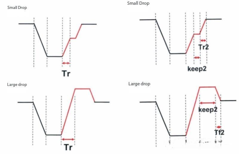
III. Coordinated Design Rules for Large and Small Droplets
| Parameter | Large Droplet (21 pL) | Small Droplet (7 pL) |
| Push Voltage | 17–17.5 V (with 43 °C ink) | ≤ 17 V (avoid trajectory shift) |
| Pulse Width | > 3 μs (increase inertia) | < 2 μs (suppress satellites) |
| Viscosity Range | 10–12 cP (risk of jet break beyond range) | Tighter control: 11 ± 0.5 cP |
Note:
For UV inks, stepped voltage waveforms are recommended (e.g., first pulse at 17 V for activation, followed by 16.2 V for tail stabilization).
Additionally, the ink supply system should be heated to 45 °C to ensure consistent flow stability.
IV. Operational and Maintenance Best Practices
1. New Printhead Break-In
- Avoid large-droplet mode during the first 72 hours
- Use small-droplet settings:
- Voltage: 16 V
- Ink temperature: 40 °C
- Gradually increase parameters to standard operating values
2. Dynamic Calibration
- After extended large-droplet operation:
- Flush internal ink residues with cleaning solution every 15–20 days
- During high-frequency small-droplet printing:
- Reduce printhead height to < 2 mm to minimize airflow disturbance
3. Shutdown Protection
- If the printer is idle for more than 3 days:
- Drain ink from the system
- Seal the nozzle plate with protective film to prevent drying and clogging
Conclusion
Droplet control in the Ricoh G5 printhead is fundamentally a synergistic optimization of fluid dynamics and piezoelectric response.
Effective waveform tuning requires real-time adjustment of waveform phase and parameters based on droplet observation system data, ensuring stable jetting and consistent print quality across both large and small droplet modes.