
Sapphire QS-256_10 AAA Inkjet Printhead Core Guidelines for Operation, Tuning, and Maintenance
I. Installation and Multi-Channel Adaptation Principles
(1) Enhanced Hardware Installation Accuracy
1. Multi-Channel Mechanical Positioning
The 256-channel architecture requires a micron-level adjustment platform to ensure:
- Nozzle-to-substrate distance deviation ≤ 0.05 mm
- Parallelism deviation < 0.02 mm/m
After installation, channel-by-channel laser alignment (rather than overall calibration) is mandatory. Even slight inter-channel tilt can cause visible color deviation.
In 10 pL small-droplet applications, a 0.03 mm distance deviation can result in over 8% fluctuation in ink coverage, directly affecting tonal uniformity.
2. Electrical Connection and Anti-Interference Optimization
- The 256 channels must be divided into four independent signal groups
- Each group must use original double-shielded cables, with outer shielding ground resistance < 0.5 Ω
- Minimum spacing between groups: ≥ 15 cm, to prevent signal crosstalk
- All connectors must be wrapped with conductive shielding tape and enclosed in metal shielding housings
This design minimizes high-frequency interference (≥ 20 kHz), particularly for edge channels.
(2) Ink Supply System Adaptation
| Parameter | Standard Specification | Impact of Deviation | Verification Frequency |
| Ink negative pressure | −2.0 to −2.8 mbar | ±0.2 mbar causes ~10% droplet volume deviation | Every 1 hour |
| Filtration precision | 3 μm titanium alloy filter | 5 μm particles can clog 10 pL nozzles (≈25 μm diameter) | Replace every 24 hours |
| Chamber pressure difference | < 0.1 mbar | > 0.15 mbar causes channel density inconsistency | At startup & after 2 h printing |
| Ink circulation flow | 0.8–1.2 L/h | Low flow increases solvent evaporation and viscosity | Every 3 hours |
II. Waveform and Small-Droplet Parameter Tuning Standards
(1) Precise Baseline Parameter Configuration
1. Initial Baseline for 10 pL Droplets (AAA Precision)
- Drive voltage: 20–26 V
Recommended starting point: 23 V; step adjustment ≤ 0.5 V - Pulse width: 1.5–2.1 μs
A 0.1 μs deviation causes ±1 pL droplet variation - Jetting frequency: 8–18 kHz
Avoid 15–17 kHz resonance zone - Rising slew rate: 35–42 V/μs
Too high → satellites; too low → jet delay
2. Deep Ink Property Matching
10 pL droplets require strict ink properties:
- Viscosity: 2.8–5 cP
- Surface tension: 32–38 mN/m
Adjustment strategies:
- Low-viscosity ink (2.8–3.5 cP):
- Pulse width: 1.5–1.7 μs
- Slew rate: 40–42 V/μs
- Reduce negative pressure to −2.2 mbar
- Medium-viscosity ink (3.5–5 cP):
- Pulse width: 1.8–2.1 μs
- Slew rate: 35–38 V/μs
- Increase circulation to 1.1–1.2 L/h
⚠ Special note:
Functional inks (quantum dot, UV-curable) require 0.1% anti-evaporation additive to prevent rapid drying at the nozzle orifice.
(2) Multi-Channel Waveform Consistency Calibration
1. Channel-by-Channel Calibration Procedure
- Capture droplet velocity and volume for all 256 channels using a droplet observation system
- Identify channels with >5% deviation
- Fine-tune affected channels:
- Pulse width ±0.05 μs or
- Voltage ±0.3 V
- Target accuracy:
- Velocity deviation ≤ 3%
- Volume deviation ≤ 2%
Save parameters in 8-channel waveform groups for rapid reuse.
2. Multi-Pulse Waveform Optimization (AAA Level)
| Application Scenario | Pulse Structure | Key Parameters |
| Satellite-free precision | Pre-pulse + main + damping post-pulse | Pre-pulse = 20% main (2 μs delay); post-pulse 1 μs @ 25% main |
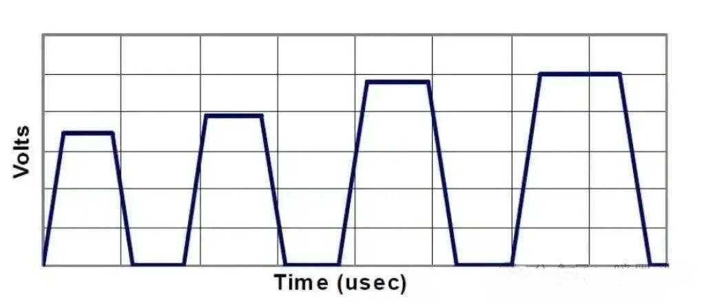
| Grayscale printing (4 levels) | Dual-main pulse | 2.2 μs spacing, voltage difference ≤ 3 V |
| High-speed (18–22 kHz) | Triple-pulse synergy | Main pulse 1.6 μs, auxiliary pulses 0.8 μs, total cycle ≤ 4.2 μs |
III. Environmental Control and Maintenance (256 Channels)
(1) Environmental Requirements
- Temperature: 22–24 °C (±0.5 °C)
- Humidity: 58–62% RH (±2%)
Above 25 °C, activate zoned water cooling (64 channels per unit), ensuring inter-zone temperature difference ≤ 0.3 °C.
Below 55% RH:
- Install humidifiers
- Add 0.2% humectant into ink supply
Cleanroom standard: Class 500
- ≥0.3 μm particles < 500/ft³
- Monitor every 4 hours
- Activate dual-stage FFU filtration if exceeded
(2) Full Maintenance Cycle (10 pL / 256 Channels)
Daily Maintenance
Startup
- Execute segmented degassing (8 channels/group, 1.5 min)
- Print 256-channel test pattern
- If abnormal channels >1%, perform targeted cleaning (5–6 ml per channel)
Shutdown
- Inject original moisturizing fluid: 0.1 ml/channel
- Use zoned sealing caps
- Replace cap sponges every 8 hours
Weekly Deep Maintenance
- Stepwise ultrasonic cleaning:
- Diluted cleaner (1:1), 40 kHz, 5 min
- Original cleaner, 35 kHz, 3 min
- Dry with low-pressure nitrogen (≤0.05 MPa)
- Verify channel consistency (≤3% deviation)
IV. Troubleshooting and Risk Prevention
(1) Common Fault Handling
| Fault | Diagnosis | Solution |
| Partial channel dropout | Check chamber pressure & drive signal | Targeted cleaning + waveform recalibration |
| Inter-channel density difference | Verify pressure & droplet volume | Adjust −0.1 mbar + ±0.3 V |
| Satellite surge | Check humidity & viscosity | Raise RH to 60%, add 0.1% additive, reduce slew rate |
| Ink starvation at high freq | Check flow & resonance | Increase flow to 1.2 L/h, avoid 15–17 kHz |
(2) Prohibited Operations (Critical)
- Never allow intra-group deviation > 1 V or 0.1 μs
- Never test 10 pL droplets at ≥ 28 V
- No shared cleaning tools between channel groups
- For shutdown >5 days: inject 0.2 ml/channel protective fluid
- Never replace filters under pressure
Final Recommendation
For AAA-level precision, the Sapphire QS-256_10 printhead requires system-level coordination between:
- Micron-level mechanical accuracy
- Channel-balanced waveform control
- Stable ink supply and environment
- Structured maintenance discipline
Only under these conditions can >95% channel uniformity and long-term printhead reliability be achieved.
Fujifilm Dimatix SKYFIRE SF600 Printhead Core Guidelines for Use and Maintenance
I. Multi-Substrate Compatibility and Installation Principles
(A) Hardware Installation and Compatibility Matching
1. Mechanical Positioning and Load Adaptation
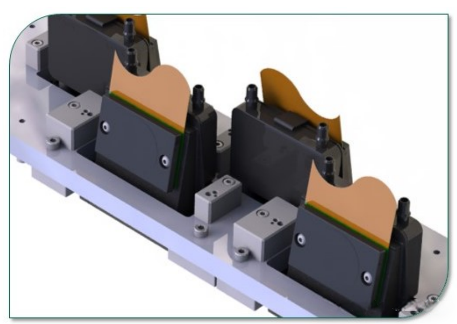
For high-throughput printing applications, the printhead must be mounted on a heavy-duty micron-level adjustment bracket (load capacity ≥ 5 kg).
Key requirements:
- Nozzle-to-substrate distance tolerance: ≤ 0.1 mm
- Parallelism deviation: < 0.03 mm/m
- Reserve ≥ 20 mm clearance for heat dissipation
- Nozzle face should be tilted downward by 0.5° (±0.1°)
This slight inclination reduces UV ink curing residue and solvent ink pooling, making it suitable for banners, PVC signage, and other mixed-media printing scenarios.
2. Electrical Connection and EMI Protection
- Drive signal cables must use original triple-shielded cables (outer copper braid + aluminum foil + inner insulation)
- Cable length: ≤ 2 m
- Connectors: gold-plated terminals (contact resistance < 0.01 Ω)
Cable routing must be divided into three independent paths:
- Drive signal lines
- Power supply lines
- Detection/feedback lines
Minimum spacing between cable groups: ≥ 20 cm
Distance from UV lamp power lines: ≥ 50 cm
This layout prevents strong electromagnetic radiation from distorting drive waveforms.
(B) Ink Supply System Adaptation for Multiple Ink Types
| Adaptation Item | Water-Based Ink | Solvent Ink | UV Ink | Verification Frequency |
| Ink Supply Pressure | +1.2 ~ +1.8 mbar | −1 ~ −2 mbar | +0.8 ~ +1.5 mbar | Every 1.5 h |
| Filtration Accuracy | 5 µm nylon filter | 3 µm stainless steel | 2 µm titanium alloy | Water/Solvent: 24 h; UV: 12 h |
| Ink Circulation Flow | 1.5–2.0 L/h | 1.0–1.5 L/h | 2.0–2.5 L/h | Every 2 h |
| Degassing Level | Vacuum ≥ −90 kPa | ≥ −95 kPa | ≥ −98 kPa | Before startup & after ink change |
II. Waveform Tuning and Multi-Ink Parameter Optimization
(A) Media-Specific Base Parameter Settings
1. Core Safety Baselines
Initial parameters must be differentiated by ink type:
- Drive Voltage
- Water-based: 18–24 V
- Solvent: 22–28 V
- UV: 20–26 V
(Single adjustment step ≤ 1 V; start from mid-range values)
- Pulse Width
- Water-based: 2.0–2.8 µs
- Solvent: 1.8–2.5 µs
- UV: 2.2–3.0 µs
(A 0.1 µs deviation may cause ±2 pL droplet volume fluctuation)
- Jetting Frequency: 8–25 kHz
(UV ink recommended ≤ 22 kHz to avoid incomplete curing) - Rising Slew Rate
- Water-based: 30–38 V/µs
- Solvent: 35–45 V/µs
- UV: 32–40 V/µs
2. Ink Property-Driven Adjustment Strategies
- Water-Based Ink (2–5 cP, 35–45 mN/m)
- Use wide pulse + low slew rate
- Pulse width: 2.5–2.8 µs
- Slew rate: 30–35 V/µs
- Increase circulation to 1.8–2.0 L/h to prevent microbial blockage
- Solvent Ink (3–8 cP, 28–35 mN/m)
- Use narrow pulse + high slew rate
- Pulse width: 1.8–2.2 µs
- Slew rate: 40–45 V/µs
- Reduce supply negative pressure to −1.5 mbar to enhance jetting force
- UV Ink (5–12 cP, 30–38 mN/m)
- Apply step-pulse waveform
- Preheat to 35 °C (viscosity reduced to 5–7 cP)
- Pulse width: 2.5–3.0 µs
- Slew rate: 35–40 V/µs
- Prevent photoinitiator-induced nozzle clogging
(B) Multi-Pulse Waveform and Application Matching
| Application Scenario | Pulse Configuration | Key Parameter Settings |
| High-Speed Banner Printing (25 kHz) | Main pulse + acceleration post-pulse | Post-pulse voltage = 30% of main, duration 1.2 µs |
| High-Precision UV Signage | Pre-pulse + main pulse + damping pulse | Pre-pulse delay 2.5 µs; damping voltage = 20% of main |
| Multi-Substrate Switching | 3-level stepped voltage pulse | Voltage difference ≤ 5 V; pulse width auto-matched to ink |
III. Environmental Control and Full-Cycle Maintenance Standards
(A) Multi-Scenario Environmental Control
1. Temperature, Humidity, and Cleanliness
- Water-Based Ink
- 20–26 °C (±1 °C)
- 50–65% RH
- Add ultrasonic humidifier if RH < 50%
- Solvent Ink
- 18–24 °C (±1 °C)
- 40–55% RH
- Forced exhaust airflow ≥ 1 m/s
- UV Ink
- 22–28 °C (±1 °C)
- 45–60% RH
- UV-shielded ventilation hood
- Distance between UV lamp and printhead ≥ 30 cm
General Cleanliness Requirement:
- Class 1000 cleanroom
- ≥0.5 µm particles < 1000 / ft³
- Measured every 6 h; activate FFU if exceeded
(B) Ink-Specific Maintenance Procedures
1. Daily Maintenance
Startup
- Water/Solvent: Ink purging + nozzle check (2 min)
- If defective nozzles > 3%, auto-clean (10 ml cleaning fluid)
- UV: Preheat at 35 °C for 10 min → UV-specific degassing
Shutdown
- Water-based: Flush with DI water → fill humidifying fluid → cap
- Solvent: Circulate cleaning solvent 3 cycles → add anti-dry agent
- UV: Flush with UV-specific cleaning fluid → inject protection fluid
2. Weekly Deep Maintenance
- Stage 1 – Surface Cleaning
Gently wipe nozzle plate with lint-free cloth soaked in matching cleaner - Stage 2 – Internal Clearing
- Water/Solvent: Ultrasonic cleaning, 40 kHz, 5 min
- UV: Heated cleaning (40 °C) + ultrasonic, 35 kHz, 8 min
- Stage 3 – Performance Verification
Droplet observation:- Velocity deviation ≤ 5%
- Volume deviation ≤ 3%
IV. Troubleshooting and Durability Protection
(A) Typical Multi-Ink Fault Handling
| Symptom | Diagnostic Focus | Solution |
| Water-based ink dropout | Filter clogging, microbial growth | Replace 5 µm filter + add 0.1% biocide |
| Solvent ink leakage | Negative pressure, seal aging | Calibrate to −1.5 mbar + replace FKM seals |
| UV curing blockage | Preheat temp, cleaner effectiveness | Raise preheat to 38 °C + decuring cleaner |
| Channel speed inconsistency | Waveform uniformity, pressure delta | Recalibrate grouped waveforms + pressure Δ < 0.2 mbar |
(B) Prohibited Operations and Lifetime Protection
1. Parameter and Operation Prohibitions
- Never reuse waveforms across ink types
- Ink path must be fully flushed (residual < 0.3 ml)
- Mixed inks cause precipitation and irreversible damage
- UV ink must not operate below 20 °C
- Preheat to ≥ 30 °C before startup
- Never blow nozzles with compressed air
- Use factory negative-pressure purging only
2. Long-Term Storage Guidelines
- Shutdown > 3 days
- Execute ink-specific sealing procedure
- Replenish sealing fluid every 3 days
- Idle > 1 month
- Remove printhead
- Vacuum-seal in original storage bag
- Store at 20–25 °C, 50–60% RH
- Prevent seal aging and nozzle oxidation