
Relationship Between Ink Droplet Placement Accuracy and Print Quality
In digital inkjet systems, the accuracy of droplet placement directly affects pattern clarity, color uniformity, and device performance. When placement accuracy requirements are better than 15 μm (corresponding to angular deviation ≤ 15 mrad) for multi‑pass applications and better than 5 μm (angular deviation ≤ 5 mrad) for single‑pass applications, the following dimensions must be analyzed:
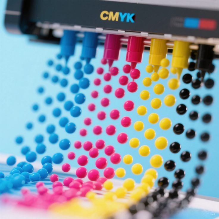
1. Cumulative Effect of Mechanical Positioning Errors
- Platform Motion Accuracy: High‑resolution printing (e.g., above 200 ppi) requires mechanical stage displacement errors to be controlled within ±10 μm; otherwise, error accumulation during multi‑drop superposition can cause pixel misalignment or edge blurring.
- Printhead Angular Deviation: If the droplet ejection angle deviates by more than 5 mrad, a 5 μm placement error will occur at a 1 mm throw distance. This directly affects the filling uniformity of sub‑pixels (55–85 μm), leading to color distortion or luminance non‑uniformity.

2. Interactive Effects of Droplet Dynamic Behavior
- Wetting Control and Coffee‑Ring Effect: Even with precise placement, droplet spreading on the substrate is influenced by surface energy, ink viscosity, etc. Angular deviation may cause asymmetric spreading, aggravating the coffee‑ring effect and reducing film uniformity.
- Tolerance for Multi‑Drop Overlap: A single‑drop deviation of 5 μm may seem small, but in high‑density printing (e.g., tens of thousands of drops per cm²), accumulated deviations can cause the overlap ratio between adjacent droplets to exceed the design threshold, resulting in uneven film thickness or functional‑layer defects.
3. System‑Level Accuracy Calibration Strategies
- Dynamic Compensation Technology: Real‑time monitoring of printhead attitude (e.g., infrared calibration) and stage position (e.g., grating encoder feedback) can correct instantaneous deviations caused by mechanical vibration or thermal deformation, stabilizing angular deviation within 5 mrad.
- Ink Formulation Optimization: Low‑surface‑tension ink can reduce trajectory drift during flight, while high‑boiling‑point solvents slow down drying, allowing droplets to slightly adjust position on the substrate, indirectly improving effective placement accuracy.

Conclusion: Precision Boundaries and Process Trade‑offs
Droplet placement accuracy must be co‑optimized with printhead physical parameters (e.g., droplet volume on the order of 10 pL) and substrate characteristics (e.g., hydrophobic patterning). For micron‑scale devices such as OLEDs, a 5 μm deviation may require redundant design (e.g., compensation zones at pixel edges); whereas for applications like advertisement printing, 15 μm accuracy combined with color‑management algorithms can already meet visual requirements.
Mechanism of Aerodynamic Effects on Ink Droplet Landing Position

1. Slipstream Interference
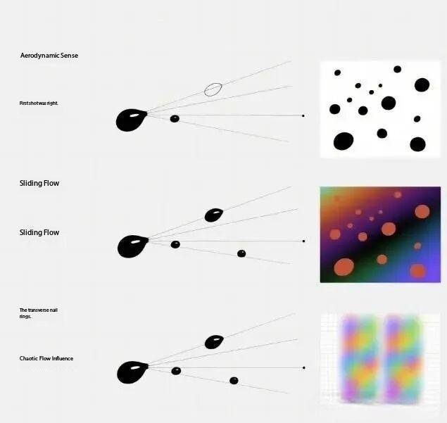
- Phenomenon: The longitudinal airflow (slipstream) generated during printhead movement alters the initial velocity vector of droplets, causing the actual landing point to deviate from the theoretical position.
- Case Example: In high‑speed printing, slipstream can cause droplets to lag or surge forward, resulting in ghosting or trailing effects.
- Key Parameters: Ratio of printhead speed to droplet mass and slipstream velocity.
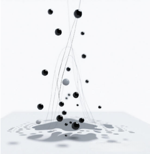
2. Crossflow Disturbance
- Cause: Ambient airflow (e.g., from ventilation equipment) or internal cooling airflow acts laterally on droplets, inducing sideways displacement.
- Impact: In wide‑format printing, crossflow can lead to uneven spacing of droplets within the same row, disrupting image continuity.
- Mitigation Measures: Installation of airflow baffles or optimization of printhead chamber sealing.
3. Turbulence Effects
- Complexity: Random vortices make droplet trajectories unpredictable, especially in multi‑printhead operations where superimposed turbulence amplifies positional errors.
- Typical Manifestation: When printing light‑colored areas, turbulence may cause uneven droplet dispersion, forming cloud‑like blotches.
- Solution: Optimize printhead array layout via CFD simulation to reduce turbulence generation.
Systematic Optimization Strategies
- Active Compensation Technology: Dynamically adjust droplet ejection timing and angle based on real‑time airflow sensor data.
- Environmental Control: Maintain constant temperature and humidity within an enclosed printing chamber to minimize external airflow interference.
- Ink Improvement: Increase ink viscosity to enhance droplet resistance to interference, while ensuring compatibility with nozzles.

Future Research Directions
It is recommended to explore the design of micro‑airflow guiding structures to reduce turbulence intensity near the printhead through directed airflow, along with developing adaptive aerodynamic compensation algorithms to respond to dynamic environmental changes.