
Waveform Editing Tool – User Guide
1. Waveform Editing Tool Interface
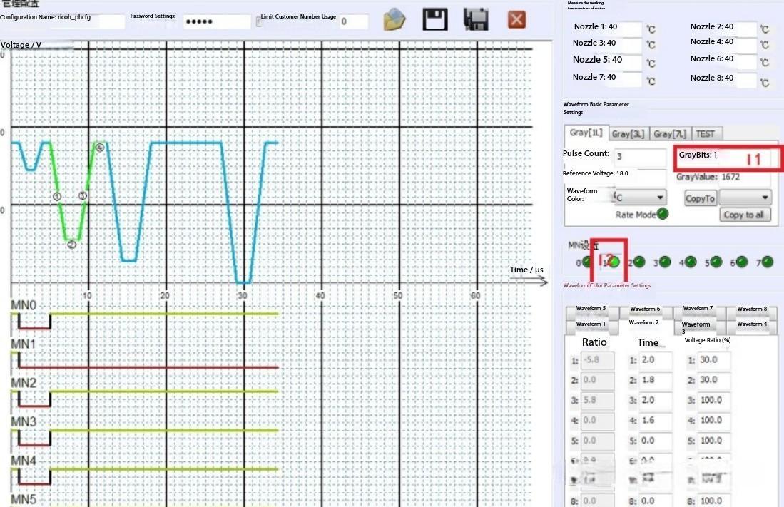
The interface of the waveform editing tool is shown below:
2. Print Parameter Configuration Interface in the Printing Software
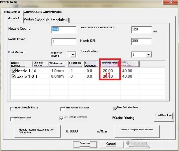
The print parameter configuration interface in the printing software is shown below:
Usage Instructions
- You can adjust the waveform according to the waveform curves provided by the ink supplier.
- You can also adjust the waveform based on the actual printing results.
Interface Operation Steps
1. Grayscale level and pulse selection
For label printing, the grayscale printing level used is 1, indicated as I1.
The number of pulses can be set to multiple values. Each pulse represents one small printed dot, provided that the MN value of that pulse is valid.
Whether a pulse is valid depends on whether I2 is selected. If the pulse shape appears like I2 (checked), that pulse is active.
2. Temperature setting
Temperature is set in the printing software.
The temperature value shown in the waveform editing tool is not used.
3. Voltage setting
Voltage can be set either in the waveform editing tool or in the printing software.
If you want to use the waveform-defined voltage, set the base voltage in the printing software to 0.
In most cases, voltage is set directly in the waveform editing tool.
4. Saving waveform parameters
After adjusting the waveform parameters, click “Copy to all”, then click I3 to save the configuration to the waveform file.
5. Loading waveforms during continuous printing
When printing multiple labels, you can click “Load waveform” in the print settings interface without closing or stopping the software.
Note: If you intend to use the base voltage (J2), first click “Apply” to save the settings, and then load the waveform.
Debugging Procedure
1. Pulse-by-pulse testing
Testing is usually performed one pulse at a time.
As shown in Figure (2), there are four pulses. The first one is a micro-motion waveform.
You can click I4 to view the waveform region corresponding to each pulse, and use I2 to enable or disable individual pulses.
2. Manual waveform editing from scratch
If you want to edit the waveform entirely by yourself, you can first set the time and voltage ratio of all waveforms to 0. In this way, only a small part of the entire waveform will appear near the origin . Then adjust the waveform according to this rule. As shown in Figure (1)
 , the duration and amplitude of the ink absorption section are adjusted at position I5 to indicate
 that the spray
 is maintained. When adjusting, adjust according to this rule.
3. Key pulse impact on print quality
Taking the waveform in the figure as an example, the last pulse has the greatest impact on print quality—this corresponds to Waveform 4 in Figure (1).
If ink misting (satellite ink) occurs, it indicates that the droplet ejection force is too high, causing splashing.
If broken lines appear, it indicates that the temperature and voltage are too high, or that the pulse period is too long.
Step-by-Step Guide to Tuning RICOH G5 / G6 Waveforms
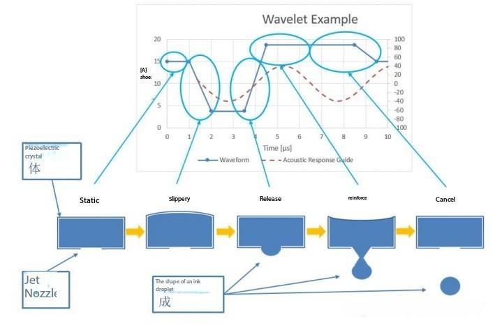
Relationship Between Waveforms and Nozzle Operating States
Relationship Between Waveforms and Data
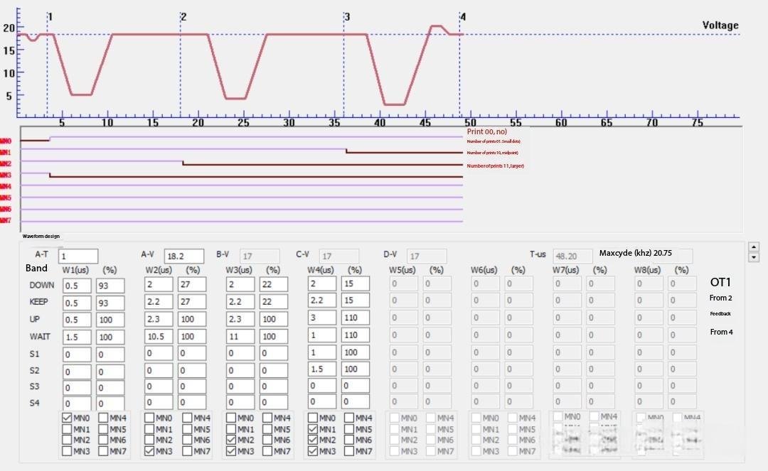
First, examine the correspondence between RIP data and waveforms.
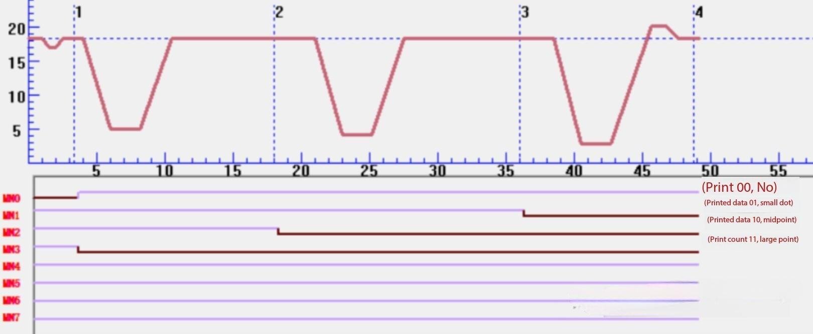
The ✓ marks above correspond to the waveform band enable switches for each dot size. In some systems, this is the main content of the so-called “waveform configuration word.”
When RIP data is received:
00 (No Ink Ejection)
- Only the stimulus (nozzle excitation) segment is enabled.
数据来时.png)
数据来时-2.jpg)
Corresponding drive waveform:
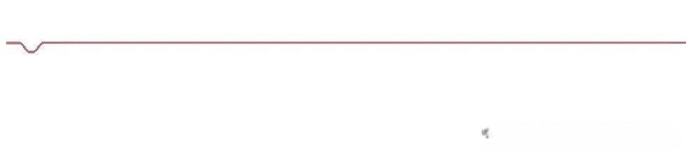
The nozzle performs only a preheating/excitation motion (no droplet formation).
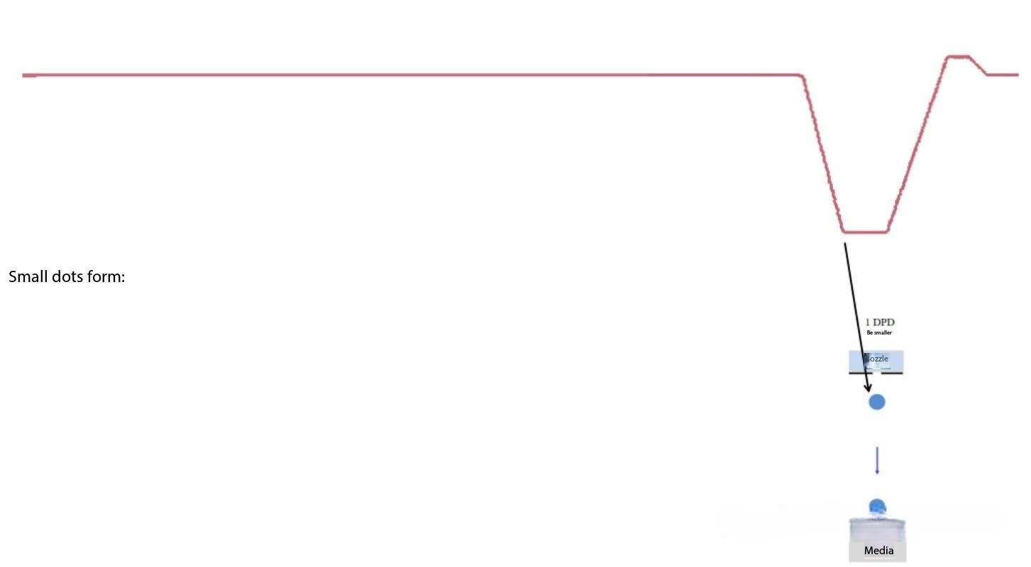
01 (Small Dot)
- The small-dot waveform segment is enabled.
数据来时.png)
数据来时-2.jpg)
Corresponding drive waveform:
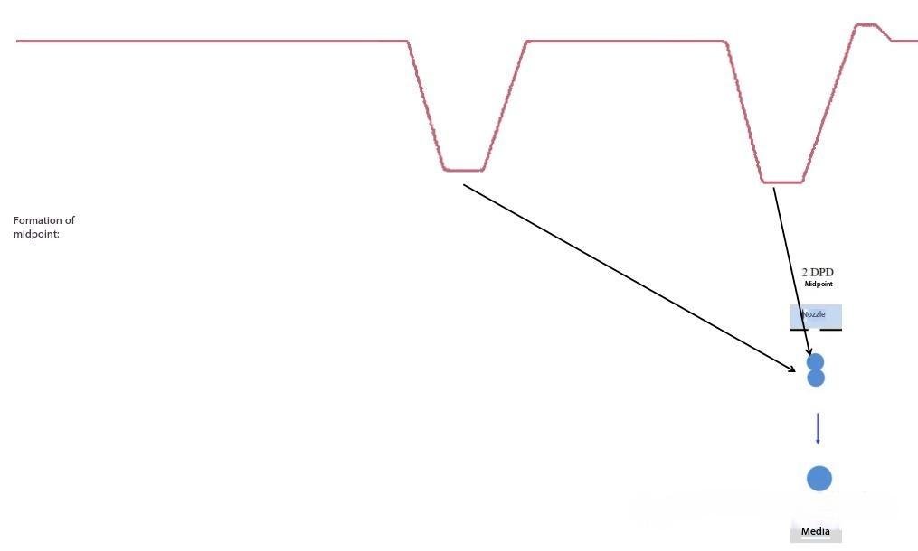
10 (Medium Dot)
- The small-dot segment and the preceding segment are enabled.
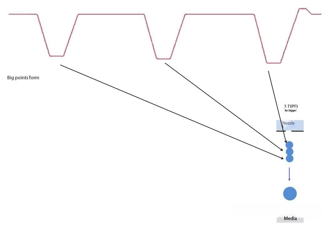
- A medium dot is formed through dot chasing (pulse superposition).
数据来时.png)
数据来时-2.jpg)
Corresponding drive waveform:
11 (Large Dot)
- The medium-dot segment and the preceding segment are enabled.
- A large dot is formed through dot chasing.
数据来时.png)
数据来时-2.jpg)
Corresponding drive waveform:
RICOH G5 / G6 Printhead Waveform Adjustment Guidelines
(Applicable to models such as MH5420 / MH5440)
Adjustments to waveform voltage and timing directly affect print quality and printhead lifespan. Fine-tuning must take into account printhead characteristics and environmental conditions.
I. Key Points for Voltage Adjustment
1. Automatic Voltage Control vs. Manual Adjustment
G5/G6 printheads support automatic voltage compensation based on ambient temperature.
Regularly verify that the actual voltage remains within the maximum theoretical limit of 24 V.
For manual adjustment, use 0.5 V increments to avoid sudden changes that may cause satellite drops or missing lines.
2. Environmental Compensation
For every 5 °C increase in temperature, reduce voltage by 0.1–0.2 V.
When humidity exceeds 70%, increase voltage compensation by approximately 0.3 V to maintain droplet stability.
3. Multi-Color Coordination
When using multi-color printheads, ensure that the voltage difference between channels does not exceed 0.3 V, otherwise color shift or nozzle deflection may occur.
II. Timing Parameter Recommendations
1. Pulse Width
High-viscosity inks require longer pulse durations (increase by 10–20 μs).
A single pulse should not exceed 50 μs, otherwise the piezo actuator may be damaged.
2. Jetting (Spitting) Frequency
Recommended frequency: 2–4 Hz.
At higher ambient temperatures, reduce frequency (e.g., 2 Hz) to prevent printhead overheating from continuous spitting.
3. Preheating Time
After power-on, allow approximately 5 minutes for printhead temperature stabilization before adjusting waveform parameters.
Temperature fluctuations directly affect droplet consistency.
III. Risk Prevention and Maintenance
Negative Pressure Monitoring
Excessive negative pressure (> 0.8 bar) can cause ink backflow. Adjust negative pressure and waveform parameters simultaneously.
Regular Calibration
Clean internal deposits every 15–20 days to prevent nozzle clogging and waveform response degradation.
Avoid Long-Term Soaking in Cleaning Fluid
Prolonged exposure to cleaning fluids can corrode adhesive layers, leading to delamination or internal nozzle blockage.
IV. Example Adjustment Procedure
- After startup, print a test pattern to evaluate the current waveform performance.
- If missing lines or ink misting occur:
- First adjust voltage (±0.5 V),
- Then fine-tune pulse width (±5 μs).
- After each adjustment, print a 4-level grayscale test chart to verify smooth tonal transitions.
If angled jetting or ghosting persists after adjustment, inspect the printhead for clogging or check the ink supply system for leakage.